
Free floating wave energy converter

a free floating wave and converter technology, applied in the field of ocean energy, can solve the problems of uneconomical cost of extracting wave energy, none has yet been fully implemented on a commercial scale, none has come up to the expectations, etc., and achieves the effect of increasing the number of flexible pipes and enhancing flow volume and pressur

Inactive Publication Date: 2010-11-02
GHOUSE SYED MOHAMMED
View PDF12 Cites 18 Cited by
  • Summary
  • Abstract
  • Description
  • Claims
  • Application Information

AI Technical Summary

Benefits of technology

"The present invention is a flexible pipe system that can extract energy from ocean waves by pumping air and water through the pipe using the wave motion. The system consists of multiple flexible pipes that are attached to the ocean surface and follow the waves as they progress. The flexible pipes have an inlet that ingests the waves and converts them into kinetic energy, which is then converted into electricity or pumped into reservoirs. The system works without any contacting components, making it more efficient and reliable. It can be used in a wave energy conversion system to provide energy from ocean waves."

Problems solved by technology

Several ocean wave energy conversion devices have since been developed, but only a few matured to full-scale trial stage, but none yet implemented fully on a commercial scale.
The main disadvantage of the wave power is the uneconomical cost of extracting wave energy.
Although several Wave Energy Converters (WEC) and more than 1000 patents exist, none seem to have come up to the expectations.
The major challenges with the state of the art WEC's have been their complexity and survivability, mainly due to the vagaries and harshness of the ocean.
This might improve the energy efficiency but not cost effectiveness—in terms of cost / kW, of the systems.
Most importantly, none of the WEC today can perhaps be implemented with the resources readily available.
Consequently, this approach increases the degree of difficulty in design, implementation, operations and maintenance of the equipment; which is quite contrary to what is required.
As such, the state of the art WEC's are commercially unviable.
However, since waves are neither steady nor concentrated enough it has not yet been possible to extract and supply wave energy viably.
The major problem with designing wave energy converters has been in handling the vast range of power variations in the ocean waves, from approximately average of 50 kW / m, peaking to 10 MW / m (a 1:200 ratio).
This translates into cost escalation, besides increasing the degree of difficulty in implementation and maintenance.
Most importantly, it is unlikely that of any WEC of today, can be implemented with generic resources.
The devices might be highly sophisticated, even more energy efficient, but perhaps, not as cost effective—in terms of cost / kW.

Method used


Image

  • Free floating wave energy converter
  • Free floating wave energy converter
  • Free floating wave energy converter

Examples


Embodiment Construction

[0043]Embodiments of the present invention will be described below specifically with reference to accompanying drawings.

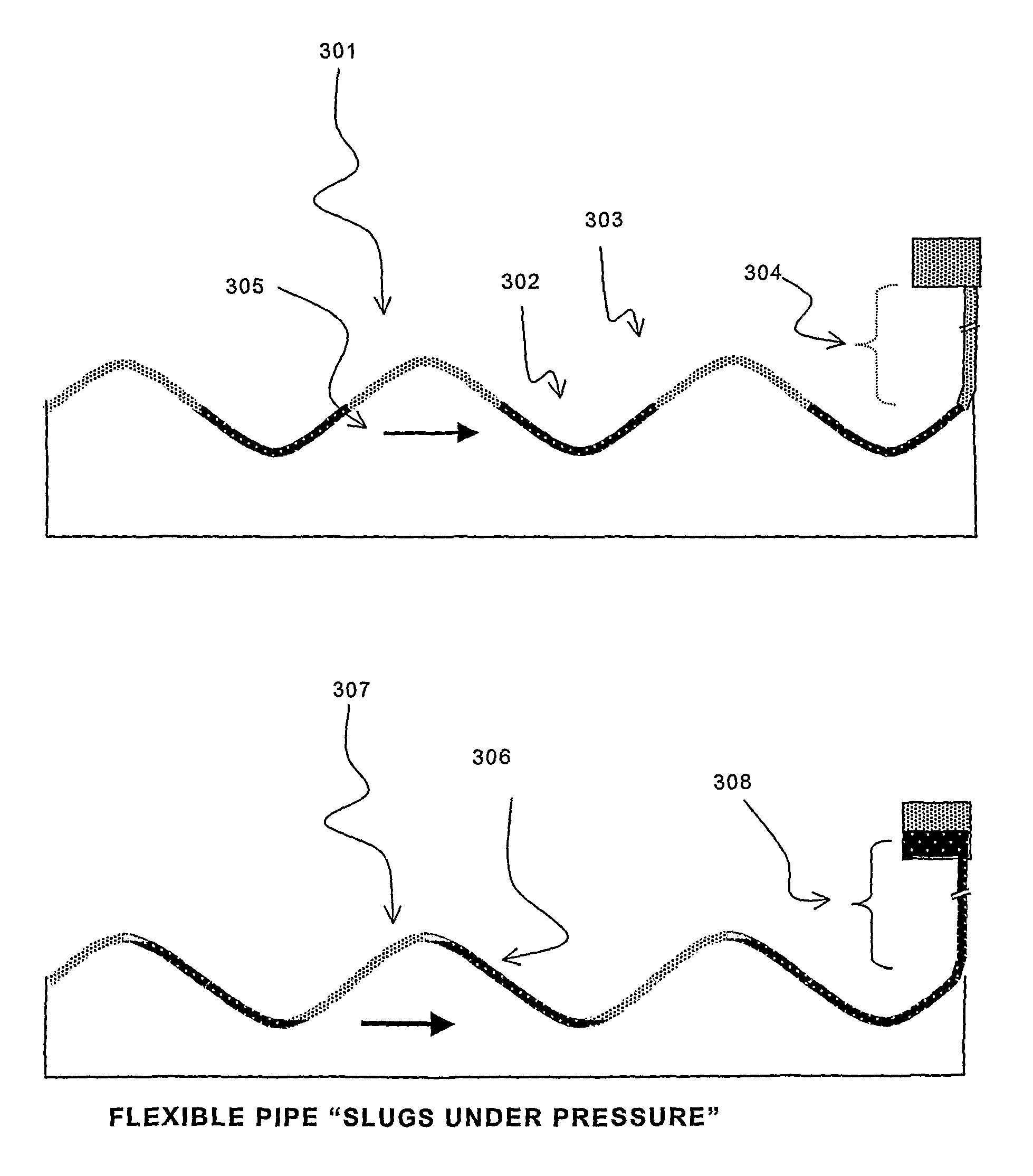
[0044]A good example of the “Flexible Pipe” WEC is surfing. As a surfer rides down a wave, it follows him, but not the water. In another example, say, if a thin and flexible sheet of impermeable material is spread out on a wave train and some water is poured on it, the water will immediately get collected in the troughs and start flowing along with the waves. Now, instead of the sheet above, let us use a hollow flexible pipe, as described in paragraph below:

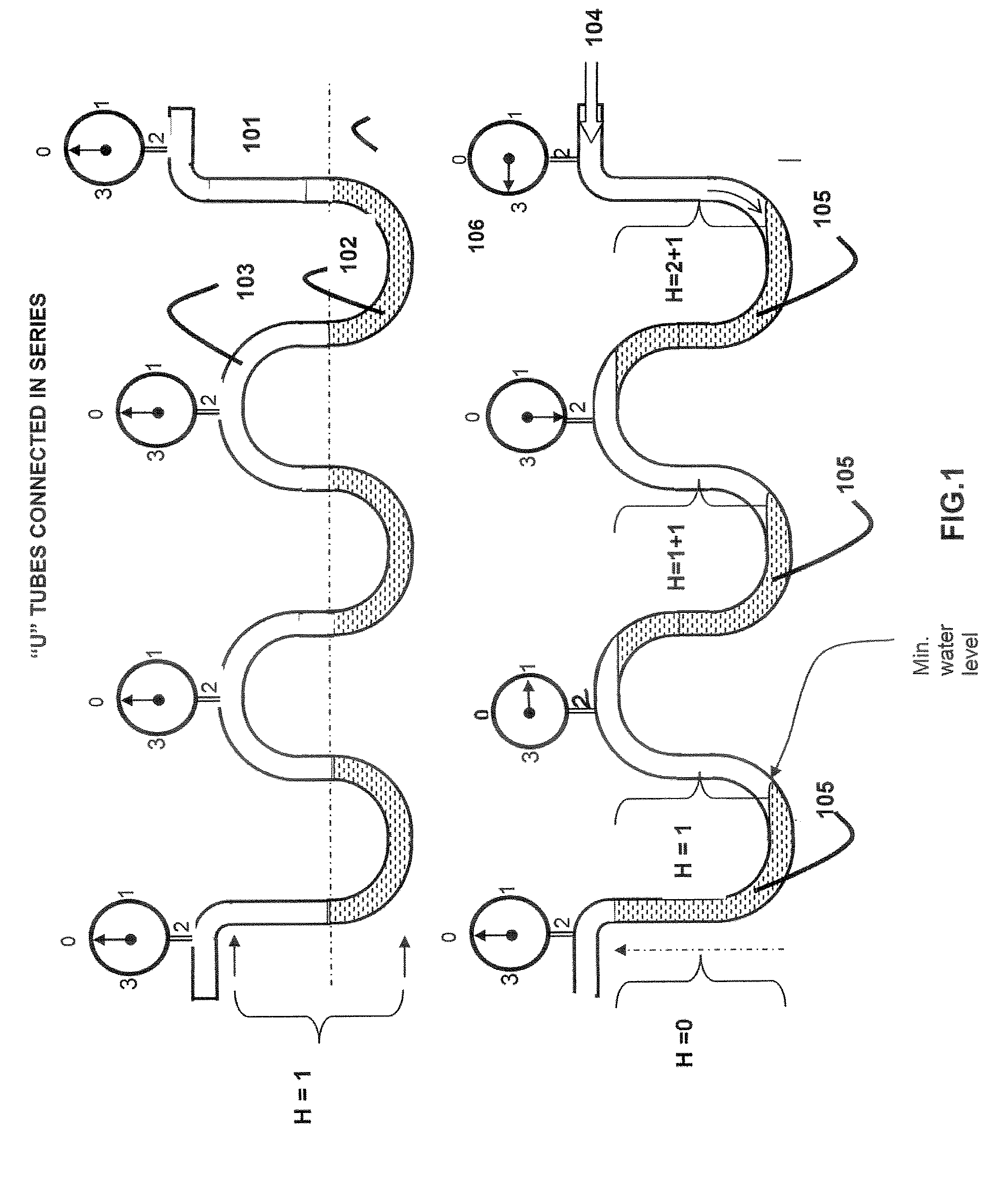
[0045]When the FFWEC is idling, i.e., with no load applied at the outlet, the water slugs remain in the trough part of the waves as it progresses. Whereas, under operating load the water slugs get pushed up the crest of the preceding wave all along the Flexible Pipe. This aspect has been illustrated at FIGS. 1(a) and (b), respectively.

[0046]FIG. 1 of the accompanying drawings illustrates the behavior of the air ...


PUM


Abstract

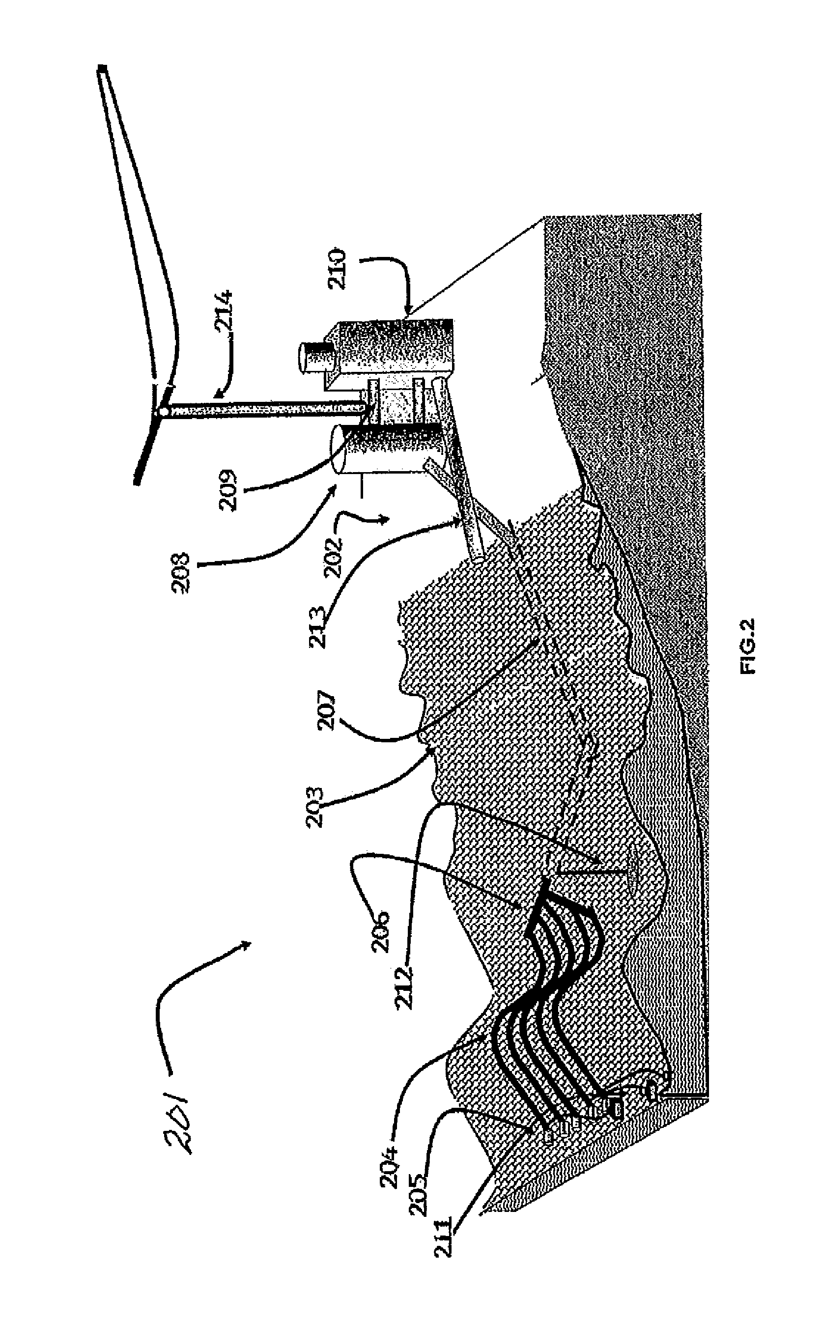
A wave energy converter includes a flexible pipe and an inlet. The flexible pipe floats on the water surface, following the wave form. Slugs of water and air enter, one after the other, through the inlet. Because the flexible pipe follows the shape of the wave, water is transported through a manifold to a pressure chamber connected to a generator. The inlet consists of a hollow, inflexible pipe attached to the throat of the flexible pipe. The inflexible pipe is fixedly attached to a buoyancy tank or plurality thereof. The buoyancy tanks are arranged in a vertical plane or in tandem, with the inflexible pipe passing along the plane vertical to the fore and aft axis of the buoyancy tank and the frontward portion projecting sufficiently ahead of the buoyancy tank with the flexible pipe terminating at a singular outlet. The entire apparatus is facing the oncoming waves.

Description

FIELD OF THE INVENTION[0001]This invention relates to ocean energy and more particularly wave energy converters (WEC). As against the rest of the state of the art WEC systems, which mostly capture energy from the undulations of waves or surge, almost all in the vertical axis, according to the present invention, energy is extracted from the wave propagation in the horizontal plane. A ‘Flexible Pipe’ floats on the surface of water and adapts to the waveform. Air and water are trapped in the pipe and segregated—due to gravity, into discrete segments or “Slugs” in the crests and troughs, respectively. The segments get pushed by the waves as they propagate from one end of it to the other. Thus, energy is extracted by virtue of the propagation of waves. The segments can flow even against pressure, if applied at the Outlet. The total pressure in a pipe will be the function of the cumulative differential pressure of all the water segments in that pipe—less losses.BACKGROUND OF THE INVENTION...

Claims


Application Information

Patent Timeline
Patent Type & Authority Patents(United States)
IPC IPC(8): F03B13/18F03B17/02
CPCF03B13/147F03B13/22Y02E10/34Y02E10/38Y02E10/30
Inventor GHOUSE, SYED MOHAMMED
Owner GHOUSE SYED MOHAMMED
Learn More