
Method to maximize hardware utilization in flow-thru IPsec processing

a technology of ipsec processing and hardware utilization, applied in the direction of transmission, electrical equipment, etc., can solve the problems of typically computation intensive functions and significant host processing overhead, and achieve the effect of facilitating offloading security processing

Active Publication Date: 2010-10-19
ADVANCED MICRO DEVICES INC
View PDF7 Cites 25 Cited by
  • Summary
  • Abstract
  • Description
  • Claims
  • Application Information

AI Technical Summary

Benefits of technology

[0009]The following presents a simplified summary of the invention in order to provide a basic understanding of some aspects of the invention. This summary is not an extensive overview of the invention. It is intended neither to identify key or critical elements of the invention nor to delineate the scope of the invention. Rather, the primary purpose of this summary is to present some concepts of the invention in a simplified form as a prelude to the more detailed description that is presented later. The invention relates to systems and methods for interfacing host systems with networks and facilitates offloading security processing from the host systems.
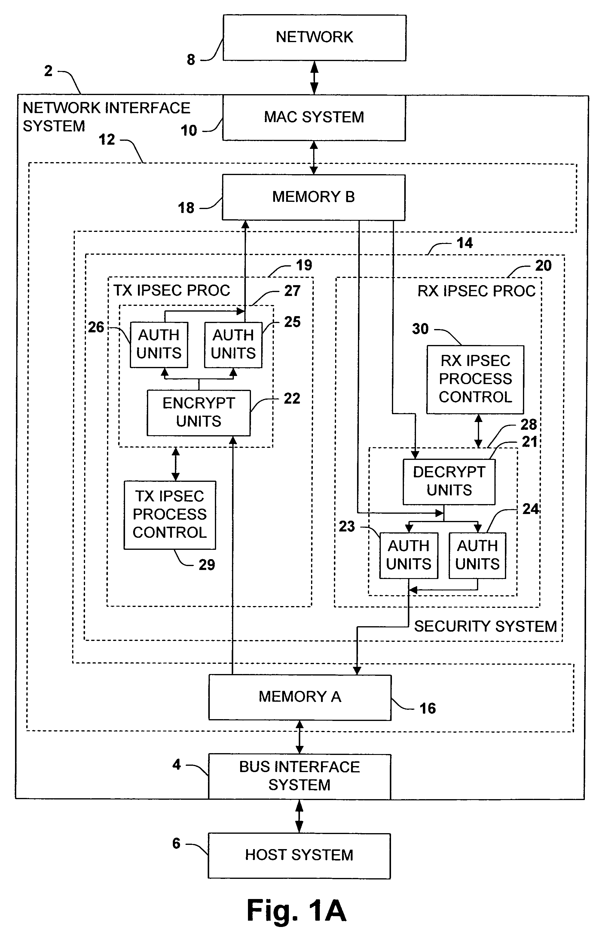
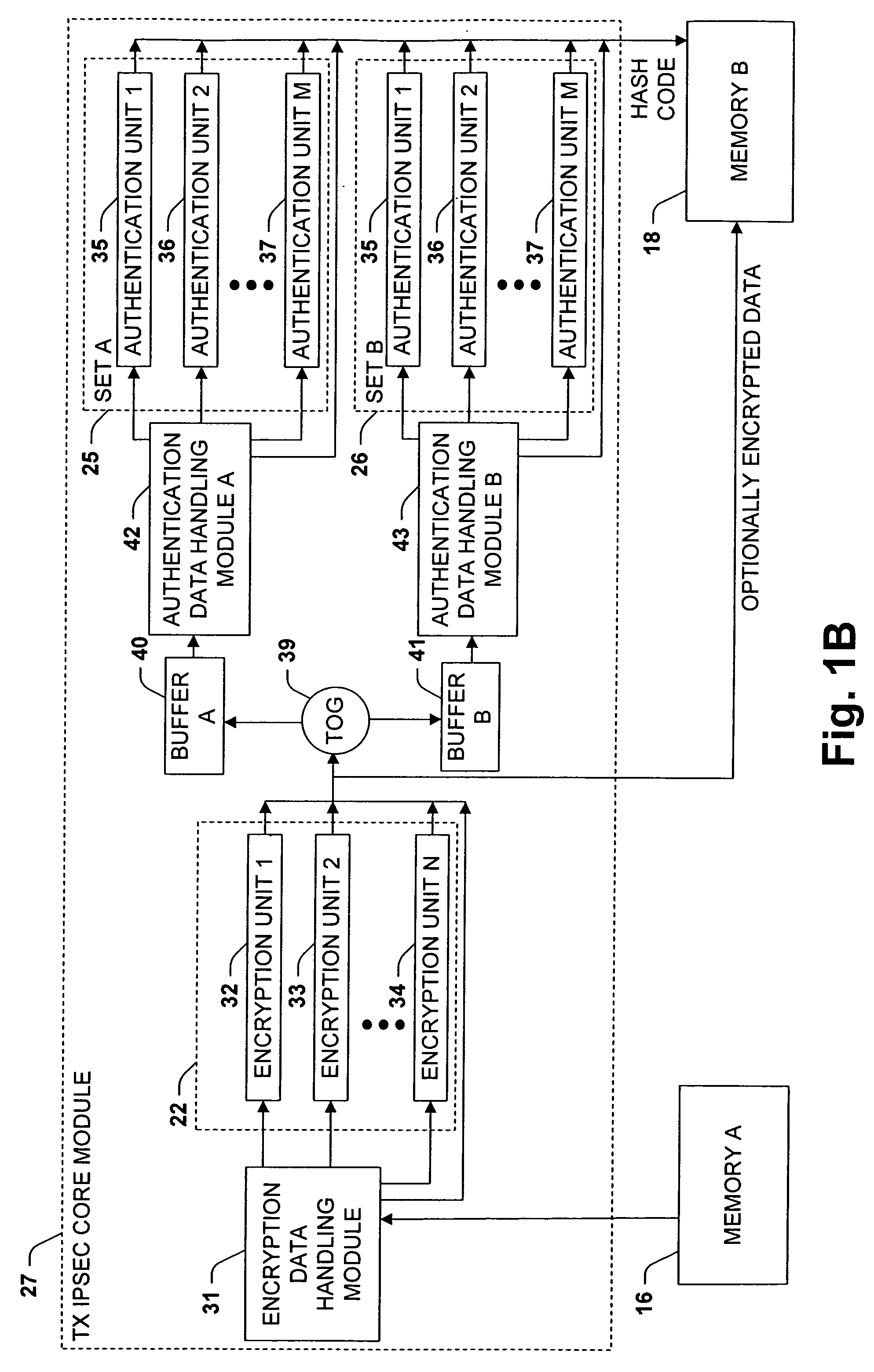
[0011]The invention facilitates high speed security processing. Commonly used authentication algorithms are slower than commonly used encryption algorithms. If only one set of authentication pipelines were used, the system would have to regularly interrupt encryption processing to allow authentication processing to “catch up”. By providing at least two sets of authentication pipelines, a potential bottleneck is removed and the encryption pipelines can remain in continuous operation.

Problems solved by technology

These functions are typically computation intensive, requiring a significant amount of host processing overhead.

Method used


Image

  • Method to maximize hardware utilization in flow-thru IPsec processing
  • Method to maximize hardware utilization in flow-thru IPsec processing
  • Method to maximize hardware utilization in flow-thru IPsec processing

Examples


Embodiment Construction

[0046]One or more implementations of the present invention will now be described with reference to the drawings, wherein like reference numerals are used to refer to like elements throughout.

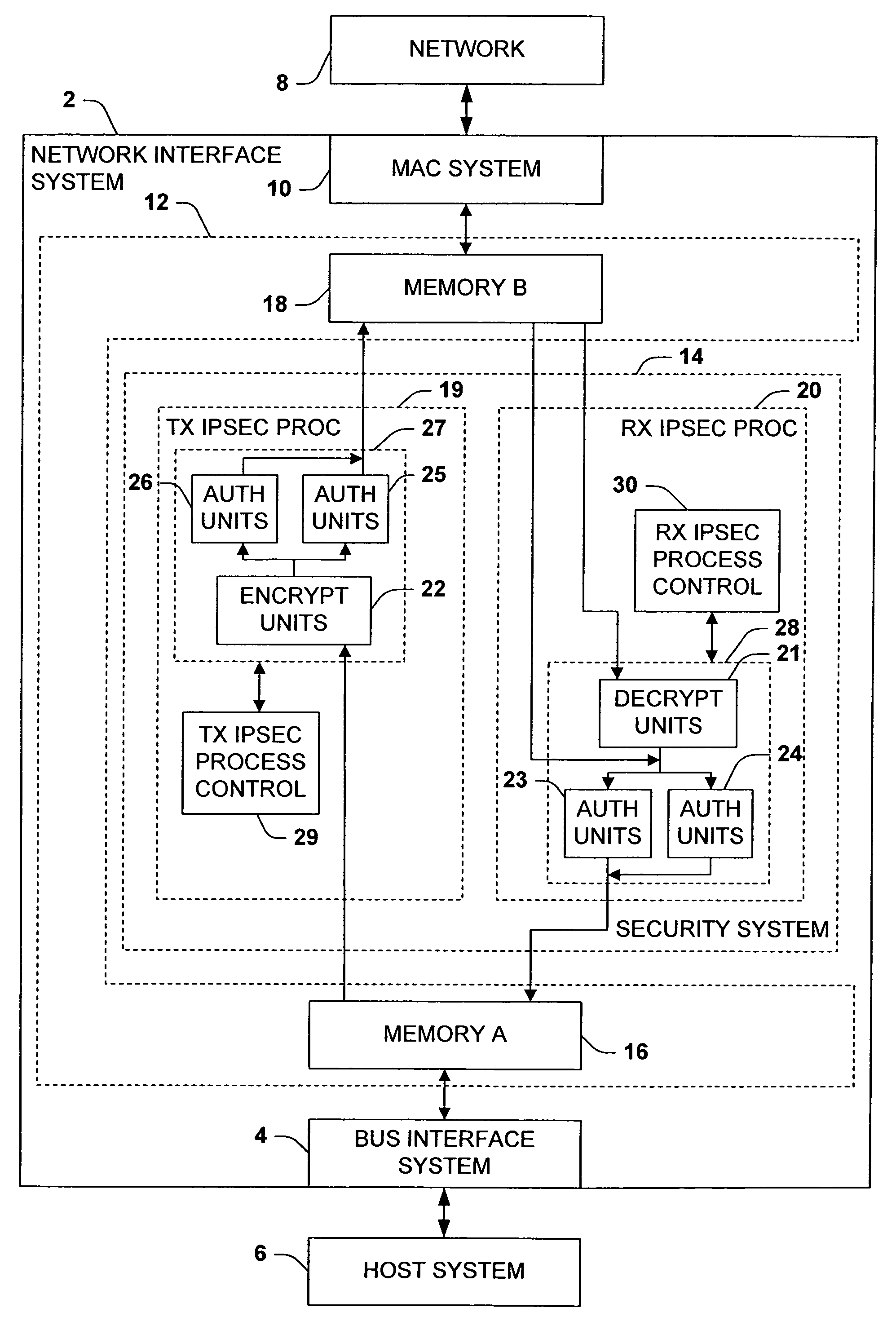
[0047]FIG. 1A illustrates an exemplary network interface system 2 for interfacing a host system 6 with a network 8, wherein the network interface system 2 is operable to provide outgoing data from the host system 6 to the network 8 and to provide incoming data from the network 8 to the host system 6. The network interface system 2 comprises a bus interface system 4 that can be operatively coupled with the host system 6, such as via a bus in the host system, and a media access control (MAC) system 10 that can be operatively coupled with the network 8, such as via a media independent interface (e.g., MII, GMII, etc.) compliant transceiver (not shown). The bus interface system 4 is adapted to transfer data between the network interface system 2 and the host system 6. The MAC system 10 is adapted to...


PUM


Abstract

The invention relates to a network interface system for interfacing a host system with a network. The network interface system includes a bus interface system, a media access control system, a memory system, and a security system. The security system is coupled to the memory system and is adapted to selectively perform security processing on incoming and outgoing data. For at least one of receive or transmit processing, the security system comprises one or more encryption pipelines and at least two sets of one or more authentication pipelines. The encryption pipelines are adapted to perform one or more encryption or decryption algorithms. The authentication pipelines are adapted to perform one or more authentication algorithms. The security system is configured to selectively process frames through the encryption pipelines and then through the two sets of authentication pipelines. The system toggles whereby successive frames alternate between the two sets of authentication pipelines.

Description

FIELD OF INVENTION[0001]The invention is generally related to the field of computer devices and more particularly to methods and systems for interfacing a host device or system with a network.BACKGROUND OF THE INVENTION[0002]Host-computing systems, such as personal computers, are often operated as nodes on a communications network, where each node is capable of receiving data from the network and transmitting data to the network. Data is transferred over a network in groups or segments, wherein the organization and segmentation of data are dictated by a network operating system protocol, and many different protocols exist. In fact, data segments that correspond to different protocols can co-exist on the same communications network. In order for a node to receive and transmit information packets, the node is equipped with a peripheral network interface device, which is responsible for transferring information between the communications network and the host system. For transmission, a...

Claims


Application Information

Patent Timeline
Patent Type & Authority Patents(United States)
IPC IPC(8): H04L29/06
CPCH04L63/0428H04L63/06H04L63/08H04L63/0485H04L63/164
Inventor DWORK, JEFFREYWILLIAMS, ROBERT ALANVISWANATH, SOMNATH
Owner ADVANCED MICRO DEVICES INC
Learn More