Radar detector with position and velocity sensitive functions

a technology of position and velocity, applied in the field of radar detectors, can solve the problems that many stationary sources cannot, as yet, be effectively filtered economically, and achieve the effects of improving the handling of such detections, effectively filtered economically, and improving the handling of unrelated sources

Active Publication Date: 2010-09-28
ESCORT INC
View PDF52 Cites 33 Cited by
  • Summary
  • Abstract
  • Description
  • Claims
  • Application Information

AI Technical Summary

Benefits of technology

[0018]The present invention overcomes these difficulties by providing a method of operating a radar detector that aids in the management of unrelated sources, and permitting the detector to dynamically improve its handling of unrelated sources. As noted above, many non-stationary sources can be identified and ignored using existing technology. However, many stationary sources cannot, as yet be effectively filtered economically with existing technology. Accordingly, the invention provides a radar detector that includes technology for determining the location of the detector, and comparing this location to the locations of known stationary sources, to improve the handling of such detections.

Problems solved by technology

However, many stationary sources cannot, as yet be effectively filtered economically with existing technology.

Method used


Image

  • Radar detector with position and velocity sensitive functions
  • Radar detector with position and velocity sensitive functions
  • Radar detector with position and velocity sensitive functions

Examples


Embodiment Construction

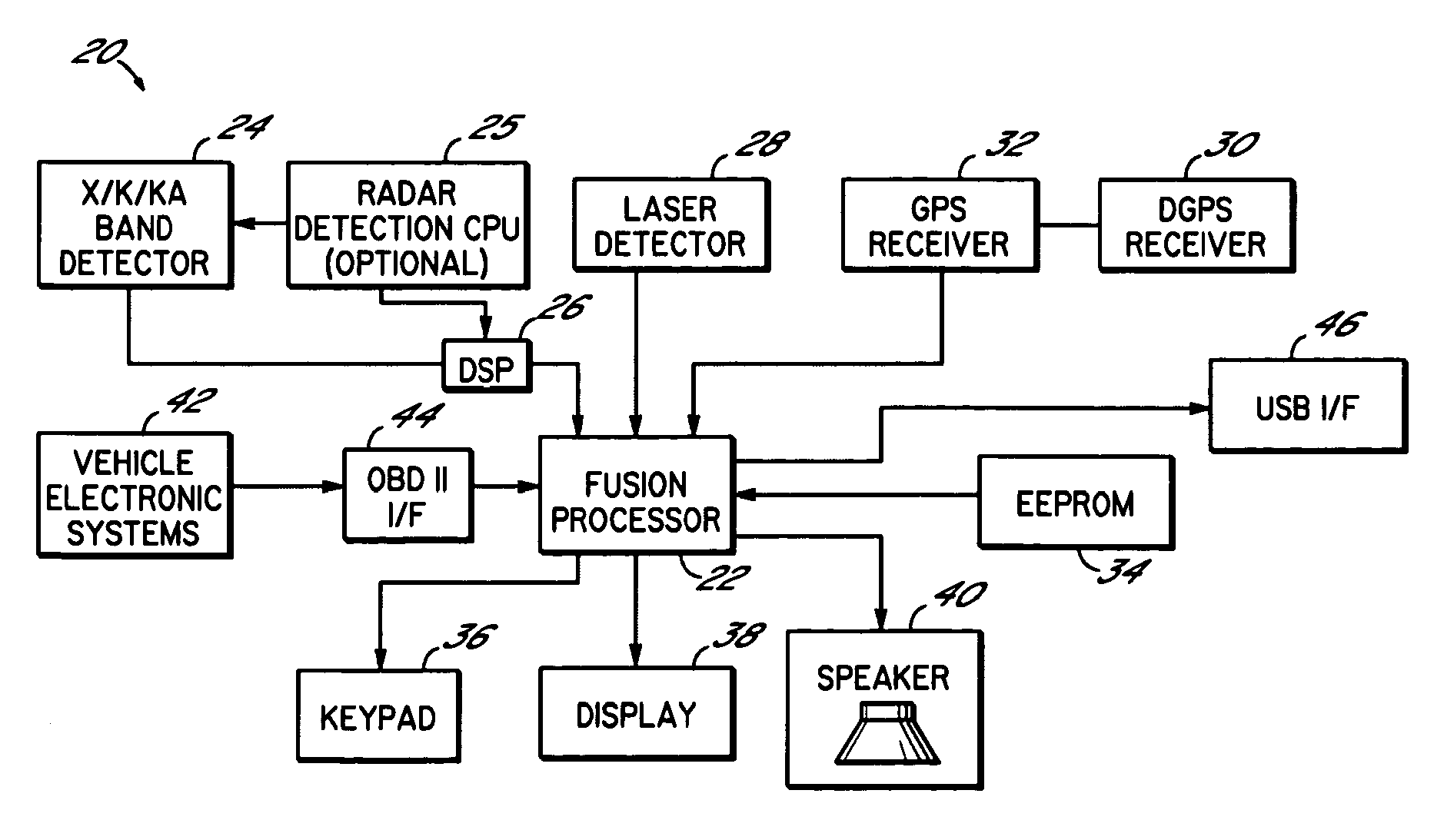
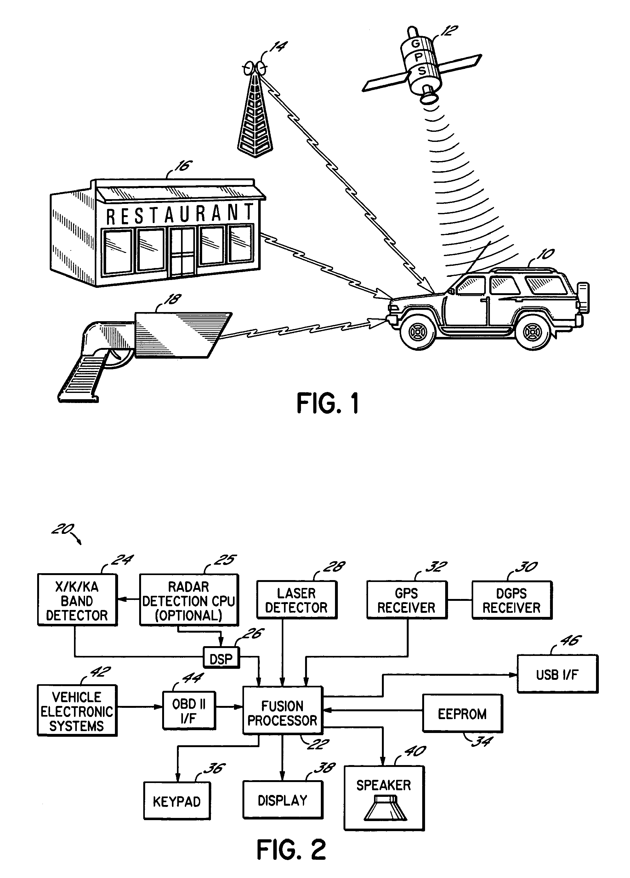
[0040]To provide background for the present invention, a summary of GPS (Global Positioning System) technology will now be provided. GPS is a mature technology that provides a method for a GPS receiver to determine its relative location and velocity at any time. The (GPS) system is a worldwide constellation of 24 satellites and their ground stations. GPS receivers on earth use ‘line of sight’ information from these satellites as reference points to calculate positions accurate to a matter of meters. Advanced forms of GPS actually enable measurements to within a centimeter. The Global Positioning System consists of three segments: a space segment of 24 orbiting satellites, a control segment that includes a control center and access to overseas command stations, and a user segment, consisting of GPS receivers and associated equipment. Over time GPS receivers have been miniaturized to just a few integrated circuits and have become very economical.

[0041]An unfortunate side effect of the...


PUM


Abstract

A GPS enabled radar detector dynamically handles radar sources based upon previously stored geographically referenced information on such sources and data from the GPS receiver. The detector includes technology for determining the location of the detector, and comparing this location to the locations of known stationary sources, to improve the handling of such detections. The detector may ignore detections received in an area known to contain a stationary source, or may only ignore specific frequencies or may handle frequencies differently based upon historic trends of spurious police radar signals at each frequency. Notification of the driver will take on a variety of forms depending on the stored information, current operating modes, and vehicle speed.

Description

CROSS-REFERENCE TO RELATED APPLICATIONS[0001]This application is a continuation in part of U.S. Ser. No. 11 / 620,443 filed Jan. 5, 2007, now U.S. Pat. No. 7,576,679, and is related to U.S. Ser. No. 10 / 396,881, filed Mar. 25, 2004, now abandoned, which is a United States divisional application of U.S. Ser. No. 09 / 889,656, filed Jul. 19, 2001 (with the declaration under Section 371(c)(4) filed Mar. 15, 2002), now U.S. Pat. No. 6,670,905, which is a U.S. National Phase of PCT / US00 / 16410 filed Jun. 14, 2000, which is a continuation-in-part of both U.S. Provisional Patent Application Ser. No. 60 / 139,097, filed Jun. 14, 1999, and U.S. Provisional Patent Application Ser. No. 60 / 145,394, filed Jul. 23, 1999, all of which are hereby incorporated herein in their entirety.FIELD OF THE INVENTION[0002]The present invention relates to radar detectors.BACKGROUND OF THE INVENTION[0003]Radar detectors warn drivers of the use of police radar, and the potential for traffic citations if the driver excee...

Claims


Application Information

Patent Timeline
Patent Type & Authority Patents(United States)
IPC IPC(8): G01S7/40H04B17/00G01S13/00
CPCG01S7/022G01S7/4806G01S19/42G01S7/04G01S19/41
Inventor ORR, STEVEN K.
Owner ESCORT INC
Why Eureka
Try Eureka