
Epitaxial oxide film, piezoelectric film, piezoelectric film element, liquid discharge head using the piezoelectric film element, and liquid discharge apparatus

a piezoelectric film and piezoelectric film technology, applied in the direction of inking apparatus, device material selection, generator/motor, etc., can solve the problems of insufficient establishment of suitable piezoelectric film elements, inability to achieve the intrinsically expected piezoelectricity, and inability to obtain piezoelectricity obtained as a result of the formation, etc., to achieve stably providing high discharge performance, reduce the size of the discharge pressure-generating element structure, and large pi

Active Publication Date: 2010-09-28
CANON KK +1
View PDF20 Cites 11 Cited by
  • Summary
  • Abstract
  • Description
  • Claims
  • Application Information

AI Technical Summary

Benefits of technology

[0014]An object of the present invention is to solve the above-mentioned problems and to provide a piezoelectric film which has large piezoelectricity and a piezoelectric film element using the piezoelectric film. Further, another object of the present invention is to provide an oxide film which has a novel structure and which can be used as a functional film in any one of various fields such as the field of an optical instrument. Still further, another object of the present invention is to provide a suitable piezoelectric film element capable of avoiding, for example, electrode peeling mainly caused by large piezoelectric distortion or film peeling upon direct formation of the piezoelectric film element directly on a substrate. Another object of the present invention is to provide a liquid discharge head capable of: stably providing high discharge performance; and reducing the size of the discharge pressure-generating element structure pattern including a piezoelectric film element, and a liquid discharge apparatus having the liquid discharge head.
[0022]According to the present invention, there can be provided a piezoelectric film element having large piezoelectricity and capable of avoiding, for example, electrode peeling in the piezoelectric film element mainly caused by large piezoelectric distortion or film peeling upon formation of the piezoelectric film element directly on a substrate, and a piezoelectric film for use in the piezoelectric film element. Further, the use of the piezoelectric film element can provide a liquid discharge head showing high uniform discharge performance and capable of additionally reducing the size of an discharge pressure-generating element structure pattern, and a liquid discharge apparatus having the liquid discharge head. In addition, according to the present invention, there can be provided an epitaxial oxide film which has a novel structure and which can be used in any one of various fields such as the field of an optical instrument.

Problems solved by technology

However, at present, the formation of a piezoelectric substrate (piezoelectric film) from such a material having high piezoelectricity as described above by a thin film formation method has not reached realization of piezoelectricity as high as one intrinsically expected, and a difference between piezoelectricity obtained as a result of the formation and that intrinsically expected is extremely large.
Further, a suitable piezoelectric film element capable of avoiding, for example, electrode peeling mainly piezoelectric distortion generated by an improvement in piezoelectricity or film peeling upon formation of the piezoelectric film element directly on a substrate has not been established yet.

Method used


Image

  • Epitaxial oxide film, piezoelectric film, piezoelectric film element, liquid discharge head using the piezoelectric film element, and liquid discharge apparatus
  • Epitaxial oxide film, piezoelectric film, piezoelectric film element, liquid discharge head using the piezoelectric film element, and liquid discharge apparatus
  • Epitaxial oxide film, piezoelectric film, piezoelectric film element, liquid discharge head using the piezoelectric film element, and liquid discharge apparatus

Examples


example 1

[0177]An oxide film and a piezoelectric film of Example 1 were produced in accordance with the following procedure.

[0178]An SrRuO3 (SRO) film having a film thickness of 200 nm was formed on an SrTiO3 {100} substrate at a substrate temperature of 600° C. by a sputtering method, whereby a substrate having an SRO lower electrode film was obtained.

[0179]Next, PZT was formed into a piezoelectric film on the substrate by employing a pulse MOCVD method. A film formation method will be described below.

[0180]The temperature of the above-mentioned substrate was heated to 600° C. while the substrate was rotated at 8.3 rpm on a substrate holder of the apparatus shown in FIG. 9. Further, a Pb raw material gas was supplied at a rate of 5.8 cm3 / min in such a manner that a ratio of the amount of a Zr raw material to the amount of Pb would be 0.14 to 0.15 and a ratio of the amount of a Ti raw material to the amount of Pb would be 0.85 to 0.86. After the above-mentioned raw material gas had been supp...

example 2

[0183]An oxide film and a piezoelectric film of Example 2 were produced in accordance with the following procedure.

[0184]The same SrTiO3 substrate with an SRO lower electrode as the substrate used in Example 1 was used.

[0185]Only a Pb raw material and a Ti raw material were used as raw material gases, and the temperature of the substrate was heated to 600° C. in the same manner as in Example 1. The Ti raw material was supplied while a ratio of the amount of the Ti raw material to be supplied to the amount of the Pb raw material gas to be supplied was set to 0.94. The number of revolutions of the substrate was set to be equal to that of Example 1, but the Pb raw material gas was supplied at a rate of 6.1 cm3 / min. Film formation was performed while the time period for which the raw materials were supplied was set to 12 seconds and the time period for which no raw material was supplied was set to 6 seconds. The operation of the 18-second period was repeated, whereby an epitaxial film h...

example 3

[0198]Next, a liquid discharge head of Example 3 was produced in accordance with the following procedure.

[0199]An SOI substrate in which an epitaxial Si film having a thickness of 500 nm and an SiO2 layer having a thickness of 500 nm had been formed was used as a substrate. After the surface of the Si {100} substrate had been treated with hydrofluoric acid, a ZrO2 film doped with Y and having a thickness of 100 nm was formed by a sputtering method at a substrate temperature of 800° C. Subsequently, a CeO2 film having a thickness of 60 nm was formed at a substrate temperature of 600° C. Each of the films was a single crystal film with a orientation. Further, an LaNiO3 (LNO) film having a thickness of 100 nm was formed as a lower electrode film on the resultant by a sputtering method at a substrate temperature of 300° C. Further, an SrRuO3 (SRO) film having a thickness of 200 nm was formed on the LNO film at a substrate temperature of 600° C., whereby a substrate having the lower ele...


PUM

PropertyMeasurementUnit
thicknessaaaaaaaaaa
thicknessaaaaaaaaaa
thicknessaaaaaaaaaa

Abstract

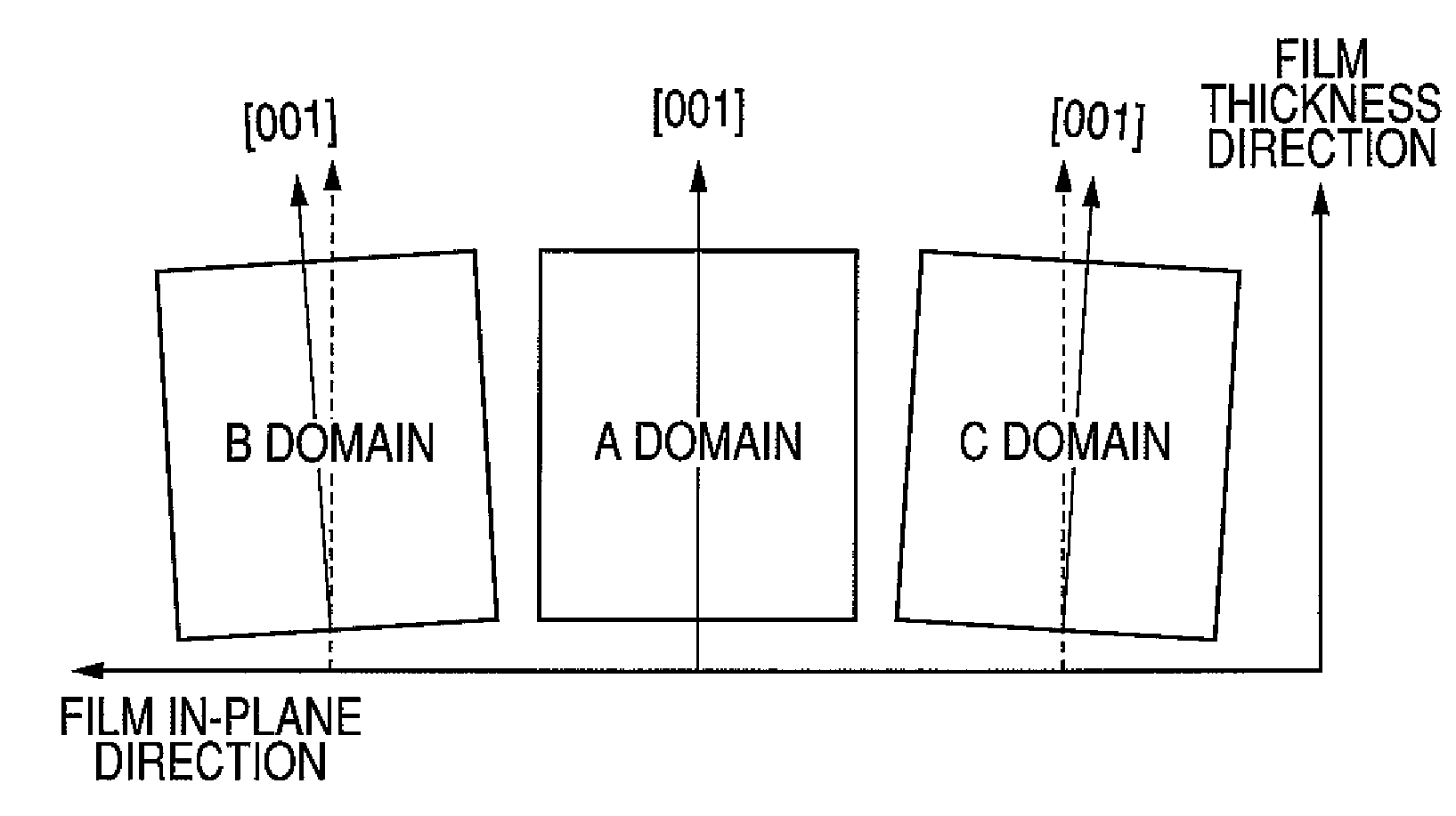
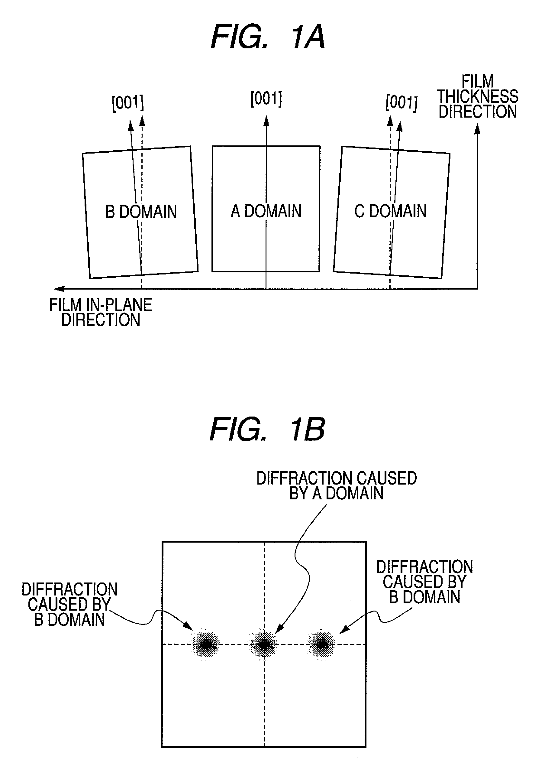
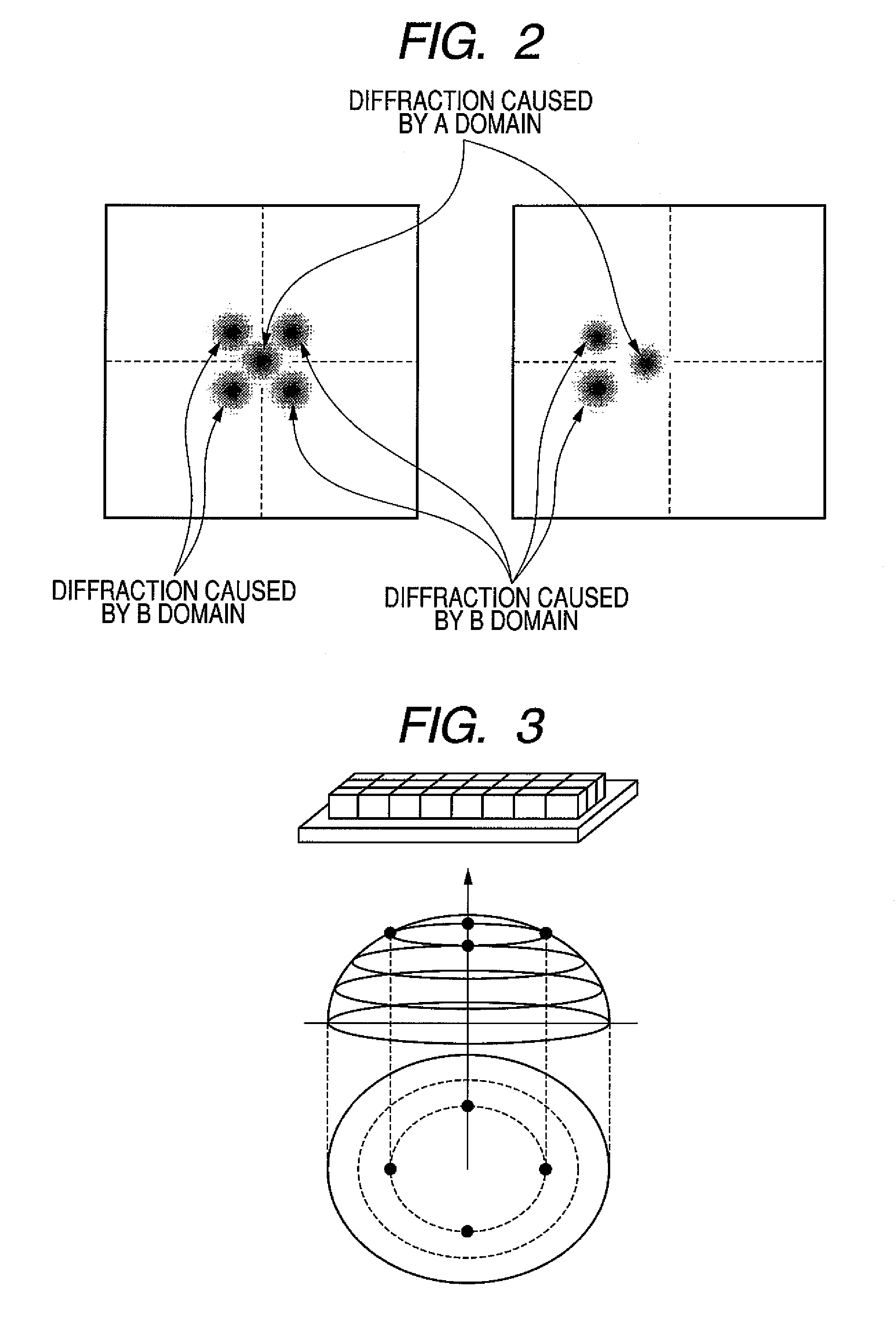
Provided are a piezoelectric film, a piezoelectric film element, a liquid discharge head using the piezoelectric film element, and a liquid discharge apparatus. A piezoelectric film element that can be suitably used for a discharge pressure-generating element of a liquid discharge head is obtained by using an epitaxial oxide film composed of a perovskite composite oxide constituted according to a general formula ABO3 as a piezoelectric film. The epitaxial oxide film has at least an A domain and a B domain having a crystal orientation deviation with respect to each other. The crystal orientation deviation between the A domain and the B domain is less than 2°.

Description

[0001]This application is a continuation of International Application No. PCT / JP2006 / 317944 filed on Sep. 5, 2006, which claims the benefit of Japanese Patent Application No. 2005-257133 filed on Sep. 5, 2005, Japanese Patent Application No. 2006-076667 filed on Mar. 20, 2006 and Japanese Patent Application No. 2006-231238 filed on Aug. 28, 2006.BACKGROUND OF THE INVENTION[0002]1. Field of the Invention[0003]The present invention relates to an epitaxial oxide film, a piezoelectric film, a piezoelectric film element, a liquid discharge head using the piezoelectric film element, and a liquid discharge head to be used particularly in a liquid discharge apparatus.[0004]2. Description of the Related Art[0005]A piezoelectric actuator can reduce a size of a motor structure and can increase density of the structure. Accordingly, the piezoelectric actuator has been recently attracting attention in a field of a portable information device and in chemical and medical fields because of its pote...

Claims


Application Information

Patent Timeline
Patent Type & Authority Patents(United States)
IPC IPC(8): H01L41/187B41J2/045B41J2/055B41J2/135B41J2/14C30B29/22C30B29/30C30B29/32H01L41/09H01L41/18
CPCB41J2/14233H01L41/1876B41J2/1623B41J2/1628B41J2/1629B41J2/1631B41J2/1632B41J2/1634B41J2/1642B41J2/1645B41J2/1646H01L41/1875H01L41/316H01L41/0805B41J2/161B41J2202/03H10N30/1051H10N30/8548H10N30/8554H10N30/076B41J2/045H10N30/20H10N30/85H10N30/853
Inventor IFUKU, TOSHIHIROAOKI, KATSUMIMATSUDA, TAKANORIFUNAKUBO, HIROSHIYOKOYAMA, SHINTAROKIM, YONG KWANNAKAKI, HIROSHIIKARIYAMA, RIKYU
Owner CANON KK
Learn More