Eureka AIR delivers breakthrough ideas for toughest innovation challenges, trusted by R&D personnel around the world.

Air duct assembly for vehicles

a technology for air ducts and vehicles, applied in the direction of combustion-air/fuel-air treatment, separation process, filtration separation, etc., can solve the problems of deteriorating the reliability of the vehicle, difficult to install the resonator according to the layout of the engine room, and affecting the comfort of driving, so as to reduce the number of working processes, reduce the noise generated, and reduce the velocity of the intake air

Active Publication Date: 2010-09-28
LEEHAN CORP
View PDF22 Cites 29 Cited by
  • Summary
  • Abstract
  • Description
  • Claims
  • Application Information

AI Technical Summary

Benefits of technology

[0011]Accordingly, the present invention has been made keeping in mind the above problems occurring in the prior art, and an object of the present invention is to provide an air duct assembly for vehicles, which reduces noise in the whole frequency range generated in an air duct, thus minimizing the transfer of noise to a driver and passenger riding in a vehicle, therefore allowing the vehicle to be traveled under stable and quiet environment.
[0012]In order to accomplish the above object, the present invention provides an air duct assembly for vehicles, including an air duct having at a first end thereof an inlet port such that fresh air outside an engine room is introduced into the air duct, and having at a second end thereof an outlet port coupled to an air cleaner, with an air hole formed in a path along which intake air flows, and a filter unit mounted to the air hole of the air duct and made of a polyurethane foam material to reduce noise of the intake air circulating through the air duct in a whole frequency range.

Problems solved by technology

When the external air is drawn and circulated, intake noise generated by the circulation of the air is transmitted to the interior of a vehicle, thus hindering comfortable driving.
However, the conventional resonator is problematic in that it is difficult to install the resonator according to the layout of an engine room.
Further, the resonator does not reliably reduce noise of a desired frequency range, thus causing noise due to unintended frequency characteristics, therefore hindering a driver or passenger riding in a vehicle from feeling comfortable, deteriorating the reliability of the vehicle and causing dissatisfaction.

Method used


Image

  • Air duct assembly for vehicles
  • Air duct assembly for vehicles
  • Air duct assembly for vehicles

Examples


Embodiment Construction

[0046]Hereinafter, an air duct assembly for vehicles according to the preferred embodiment of the present invention will be described with reference to the accompanying drawings.

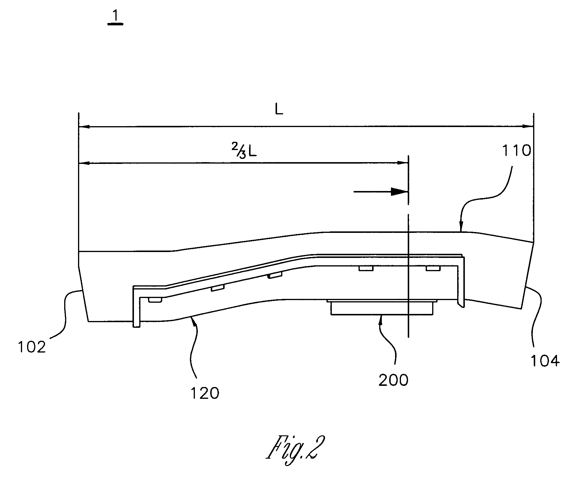
[0047]Referring to FIGS. 1 to 19a and 19b, the air duct assembly 1 for vehicles according to the present invention includes an air duct 100 and a filter unit 200. The air duct 100 has on one end thereof an inlet port 102 such that fresh air outside an engine room is introduced into the air duct 100, and has on the other end an outlet port 104 which is coupled to an air cleaner 2. Further, an air hole 106 is formed in the air duct 100 on a path along which intake air flows. The filter unit 200 having a plurality of pores is attached to the air hole 106 of the air duct 100 and functions to reduce noise of the intake air which circulates through the air duct 100 in the whole frequency range.

[0048]The air hole 106 formed in the air duct 100 according to the present invention is placed adjacent to the air cleaner...


PUM

PropertyMeasurementUnit
frequencyaaaaaaaaaa
thicknessaaaaaaaaaa
thicknessaaaaaaaaaa

Abstract

Disclosed herein is an air duct assembly for vehicles which reduces noise generated by the flow of intake air which flows along a path of the air duct provided in a vehicle and is fed to an engine. The air duct reduces the noise of a low frequency range in initial engine start operation, and in addition, the noise of a whole frequency range, thus allowing a vehicle to be traveled while providing the environment having minimum noise to a driver and passenger riding in the vehicle. Therefore, it is not necessary to install an additional resonator.

Description

RELATED APPLICATIONS[0001]This application claims priority under 35 U.S.C. 119 to Korean Patent Application No. 10-2007-0129347, filed Dec. 12, 2007; Korean Patent Application No. 10-2008-0058337, filed Jun. 20, 2008; and Korean Patent Application No. 10-2008-0121458, filed Dec. 2, 2008, which applications are incorporated herein by reference and made a part hereof.BACKGROUND OF THE INVENTION[0002]1. Field of the Invention[0003]The present invention relates to an air duct assembly for vehicles, in which a filter for reducing noise over the whole frequency range is mounted to an air duct installed in a vehicle, thus effectively reducing noise which is generated as external air is drawn into the vehicle from an initial starting operation to a high-speed running operation, therefore providing a quiet environment.[0004]2. Description of the Related Art[0005]Generally, an intake system for vehicles includes an air cleaner, an air intake hose, a throttle body and an intake manifold. The a...

Claims


Application Information

Patent Timeline
Patent Type & Authority Patents(United States)
IPC IPC(8): E04F17/04B01D50/00F02M35/00B01D39/00
CPCB01D46/10B01D46/4236F02M35/1272F02M35/14F02M35/1211F02M35/1238F02M35/024B01D2275/40
Inventor PARK, MIN-YONGMOON, HYUNG-KISHIN, IN-SU
Owner LEEHAN CORP
Why Eureka
Eureka Blog
Learn More