Resonant fiber optic gyroscope coherent demodulation system and method based on external beam interference
What is Al technical title?
Al technical title is built by PatSnap Al team. It summarizes the technical point description of the patent document.
A beam and source resonance technology, applied in Sagnac effect gyroscopes and other directions, can solve the problems of inability to completely suppress laser frequency noise, semiconductor laser high frequency noise, etc., to reduce laser frequency noise, clear signal spectrum, reduce effect of influence
Active Publication Date: 2020-05-19
ZHEJIANG UNIV
View PDF7 Cites 0 Cited by
Summary
Abstract
Description
Claims
Application Information
AI Technical Summary
This helps you quickly interpret patents by identifying the three key elements:
Problems solved by technology
Method used
Benefits of technology
Problems solved by technology
[0006] From the perspective of system miniaturization, a semiconductor laser with a smaller volume is more suitable as a system light source for a resonant fiber optic gyroscope, but the semiconductor laser itself has greater frequency noise than a fiber laser, and the PDH laser frequency locking technology is limited Due to the noise suppression bandwidth, it only has a good suppression effect on frequency noise at low frequencies, and has no suppression effect on white noise at high frequencies.
Therefore, the existing laser frequency noise suppression scheme cannot completely suppress the laser frequency noise in the miniaturized resonator fiber optic gyroscope
Method used
Image
Click on the blue label to locate the original text in one second.
Reading with bidirectional positioning of images and text.
Examples
Embodiment Construction
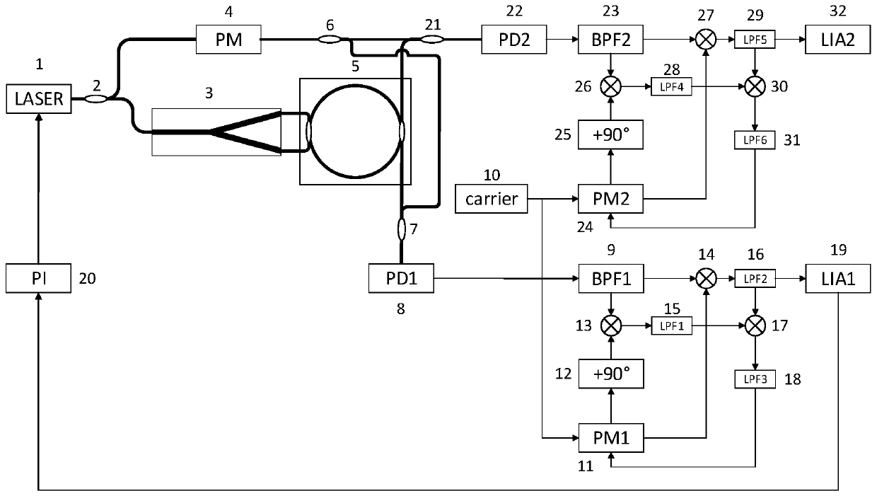
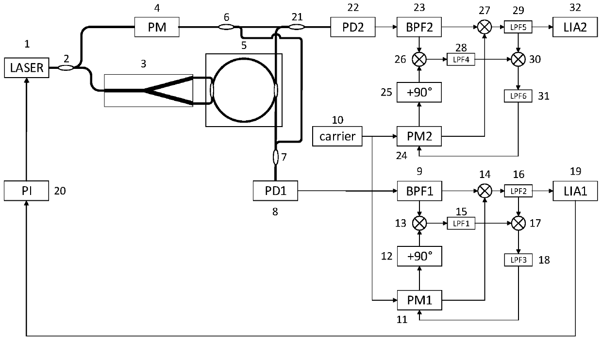
[0022] Such as figure 1As shown, a resonant fiber optic gyro coherent demodulation system based on external beam interference includes a laser 1, a first polarization-maintaining coupler 2, a Y-branch phase modulator 3, a phase modulator 4, a fiber resonator 5, and a second polarization-maintaining coupler A bias coupler 6, a third polarization maintaining coupler 7, a first photodetector 8, a first bandpass filter 9, a second photodetector 10, a local carrier generation module 10, a first local carrier phase shift module 11, 90 ° phase shift module 12, the first multiplier 13, the second multiplier 14, the first low-pass filter 15, the second low-pass filter 16, the third multiplier 17, the third low-pass filter 18, the first A digital lock-in amplifier 19, a PI servo loop 20, a fourth polarization maintaining coupler 21, a second photodetector 22, a second bandpass filter 23, a second local carrier phase shift module 24, and a second 90° phase shift Module 25, the fourth mu...
PUM
Abstract
The invention discloses a resonant type fiber-optic gyro coherent demodulation system and method based on interference of externally added light beams. The system includes a laser, a first polarization-maintaining coupler, a Y-branch phase modulator, a phase modulator, an optical fiber resonant cavity, a second polarization-maintaining coupler, a third polarization-maintaining coupler, a first photoelectric detector, a first band-pass filter, a local carrier generation module, a first local carrier phase shift module, a first 90-degree phase shift module, a first multiplier, a second multiplier, a first low-pass filter, a second low-pass filter, a third multiplier, a third low-pass filter, a first digital phase-lock amplifier, a PI servo loop, a fourth polarization-maintaining coupler, a second photoelectric detector, a second band-pass filter, a second local carrier phase shift module, a second 90-degree phase shift module, a fourth multiplier, a fifth multiplier, a fourth low-pass filter, a fifth low-pass filter, a sixth multiplier, a sixth low-pass filter, and a second digital phase-lock amplifier. By local recovery of a carrier with high signal-to-noise ratio, the signal-to-noise ratio of a demodulated signal is improved, the influence of laser frequency noise is reduced, and the resonant type fiber-optic gyro coherent demodulation system and method have important scientific significance and application value.
Description
technical field [0001] The invention relates to a resonant optical fiber gyroscope demodulation system and method for locking an optical passive resonant cavity resonant cavity by interference of externally applied coherent light, so as to suppress laser frequency noise in the resonant optical fiber gyroscope. Background technique [0002] The resonant fiber optic gyro is an inertial angular velocity sensor based on the Sagnac effect. It uses the frequency difference between the clockwise and counterclockwise resonant frequencies of the resonant cavity caused by the Sagnac phase shift generated by the rotation to measure the rotational angular velocity. Compared with the interferometric fiber optic gyroscope, the resonant fiber optic gyroscope uses the laser to transmit multiple times in the resonant cavity to amplify the Sagnac effect, and achieve the same limit sensitivity as the interferometric fiber optic gyroscope with shorter optical fibers. It has the characteristics ...
Claims
Application Information
Patent Timeline
Application Date:The date an application was filed.
Publication Date:The date a patent or application was officially published.
First Publication Date:The earliest publication date of a patent with the same application number.
Issue Date:Publication date of the patent grant document.
PCT Entry Date:The Entry date of PCT National Phase.
Estimated Expiry Date:The statutory expiry date of a patent right according to the Patent Law, and it is the longest term of protection that the patent right can achieve without the termination of the patent right due to other reasons(Term extension factor has been taken into account ).
Invalid Date:Actual expiry date is based on effective date or publication date of legal transaction data of invalid patent.