Developing apparatus and electrophotographic image-forming apparatus

a technology of developing apparatus and electrophotography, which is applied in the direction of electrographic process apparatus, instruments, developers, etc., can solve the problem that the latent image on the photosensitive drum is difficult to develop with the developer from the developing sleeve, and achieve the effect of suppressing the fluctuation in image density

Inactive Publication Date: 2010-09-14
CANON KK
View PDF9 Cites 24 Cited by
  • Summary
  • Abstract
  • Description
  • Claims
  • Application Information

AI Technical Summary

Benefits of technology

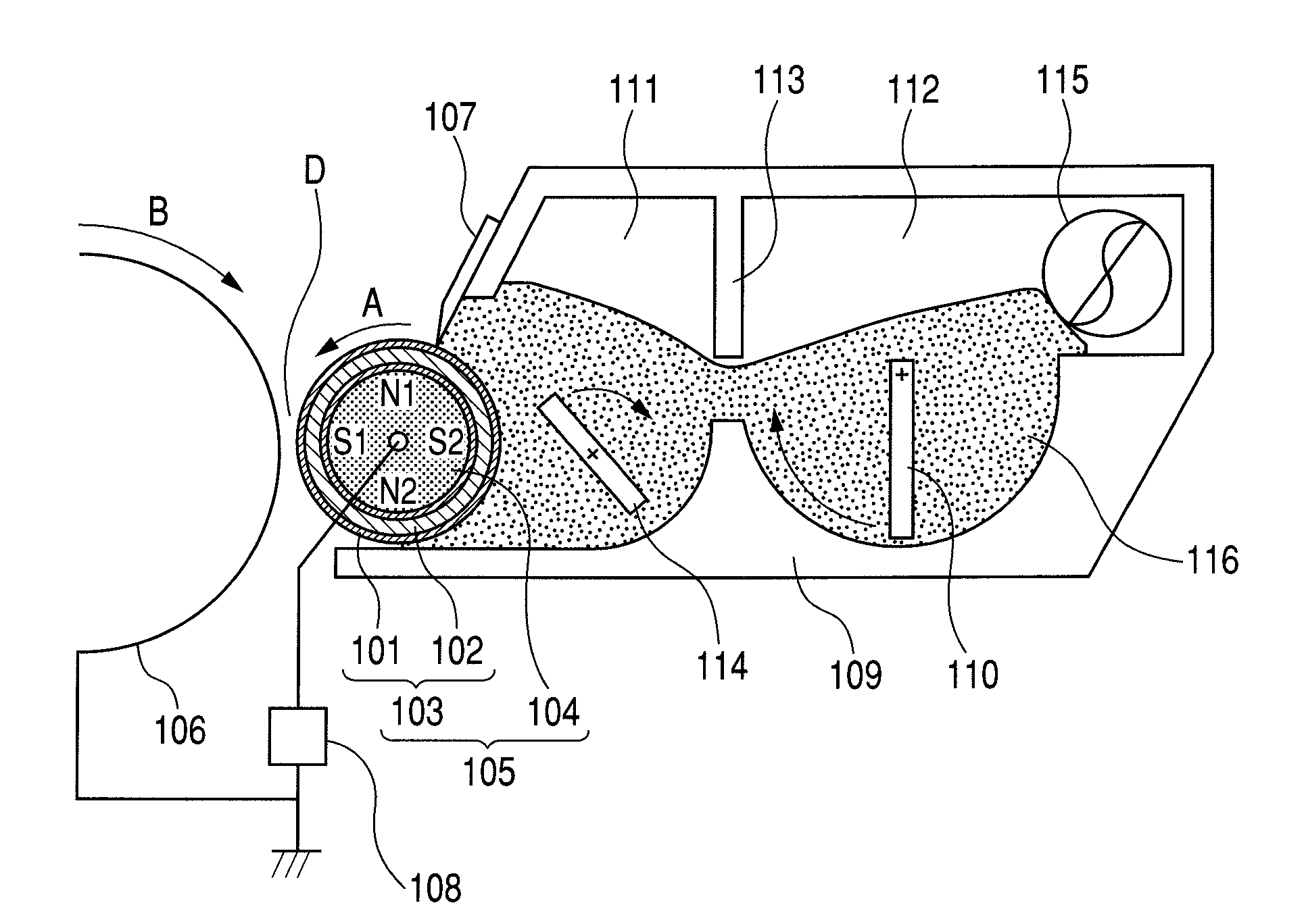
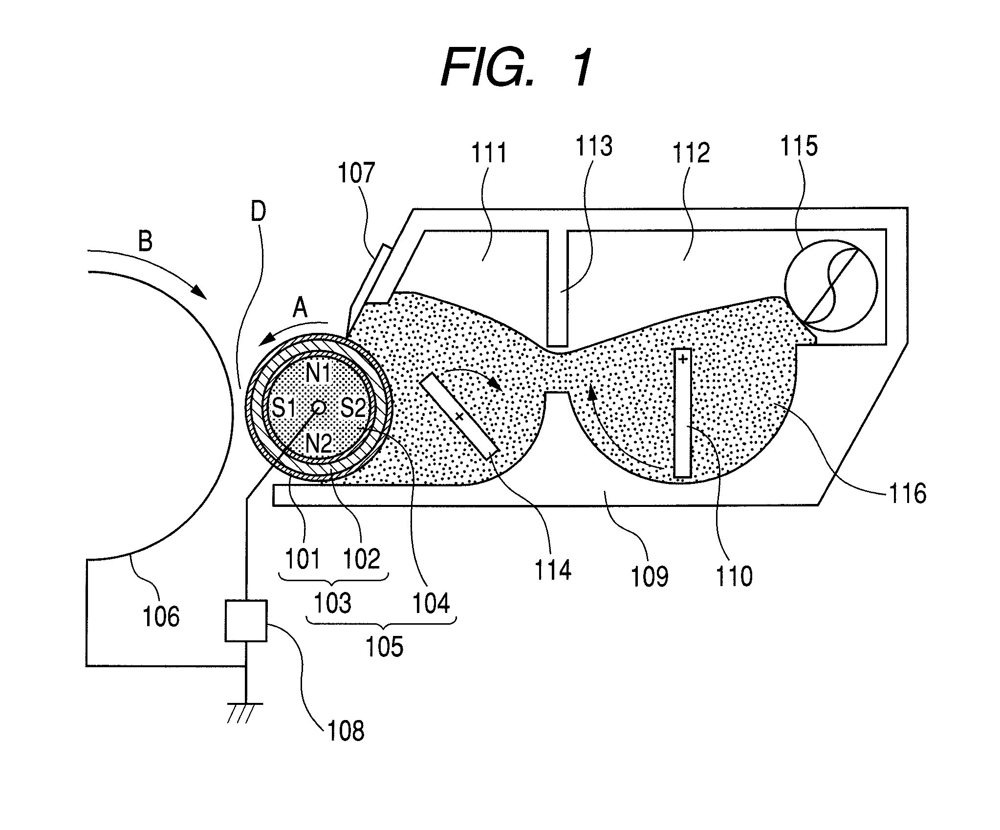
[0011]The inventors of the present invention have made investigation into the above-mentioned increase of image density occurring after a pause. As a result, the inventors have found the correlation between the increase and the charge-up of a developer. That is, the inventors have considered as follows: mirror force affecting the developer which has undergone charge-up owing to extensive operation is weakened by setting a pause period, and an image can be easily developed with the developer at the time of printing after a pause, whereby an image density increases.
[0015]As described above, according to the present invention, a fluctuation in image density can be suppressed even in a discontinuous printing mode provided with a pause period.

Problems solved by technology

However, when the amount of a magnetic material is reduced and the particle size of a developer is reduced, a so-called charge-up phenomenon as described below is apt to occur: the developer is brought into a passive state by mirror image force with the surface of a developing sleeve, so a latent image on a photosensitive drum is difficult to develop with the developer from the developing sleeve.

Method used


Image

  • Developing apparatus and electrophotographic image-forming apparatus
  • Developing apparatus and electrophotographic image-forming apparatus
  • Developing apparatus and electrophotographic image-forming apparatus

Examples


example 1

[0385]

[0386]A developer bearing member g-1 to be combined with the developer c-1 prepared in advance was produced by the following method. First, the following materials were mixed, and the mixture was treated with a horizontal sand mill (filled with glass beads having a diameter of 0.6 mm in the packing ratio of 85%), whereby a primary dispersion liquid h-1 was obtained.

[0387]

Binder resin l-1166.7 parts by mass(solid content 100 parts by mass)Graphitized particles b-1  90 parts by massCarbon black  10 parts by massMethanol133.3 parts by mass

[0388]Next, the following materials were mixed, and the mixture was treated with a vertical sand mill (filled with glass beads having a diameter of 0.8 mm in the packing ratio of 50%), whereby a secondary dispersion liquid i-1 was obtained. Further, the dispersion liquid was diluted with methanol, whereby a coating liquid j-1 having a solid content of 37% was obtained.

[0389]

Primary dispersion liquid h-1400 parts by mass(solid content 200 parts b...

examples 2 to 8

[0438]A developer to be combined with the above developer bearing member g-1 was changed as shown in Table 6. Table 6 shows various numerical values representing the surface shape of the developer bearing member g-1 in relation to each developer. In addition, image evaluation was performed in the same manner as in Example 1 except that an electrophotographic image-forming apparatus according to each combination was used. Table 7 shows the results.

example 9

[0439]A developer bearing member g-2 to be combined with the developer c-1 was produced as described below. In other words, the developer bearing member g-2 was produced in the same manner as in the developer bearing member g-1except that the graphitized particles d-1 used in the production of the above-mentioned developer bearing member g-1 were changed to the graphitized particles d-2. Table 6 shows various numerical values representing the surface shape of the developer bearing member g-2 in relation to the developer c-1. In addition, image evaluation was performed in the same manner as in Example 1 except that an electrophotographic image-forming apparatus in which the developer c-1 and the developer bearing member g-2 were combined with each other was used. Table 7 shows the results.


PUM


Abstract

A developing apparatus is provided which can suppress a fluctuation in image density in a discontinuous printing mode provided with a pause period. The developing apparatus includes a developer for developing an electrostatic latent image on a photosensitive drum, a developer bearing member for carrying and conveying the developer and a developer layer thickness-regulating unit placed close to the developer bearing member for regulating the amount of the developer carried and conveyed by the developer bearing member, the developer layer thickness-regulating unit being. As the developer, a negatively chargeable, one-component, magnetic toner is used having magnetic toner particles containing a binder resin and a magnetic iron oxide particle, and has a specific saturation magnetization, specific weight-average particle diameter and specific composition. The developer bearing member includes a surface layer containing a binder resin, a quaternary ammonium salt, graphitized particles, and conductive, spherical resin particles, and has a specific surface shape.

Description

[0001]This application is a continuation of International Application No. PCT / JP2009 / 052254, filed on Feb. 4, 2009, which claims the benefit of Japanese Patent Application No. 2008-037419 filed on Feb. 19, 2008.BACKGROUND OF THE INVENTION[0002]1. Field of the Invention[0003]The present invention relates to a developing apparatus to be used for developing an electrostatic latent image formed on an electrostatic latent image-bearing member such as a photosensitive member or an electrostatic recording derivative, and an electrophotographic image-forming apparatus including the developing apparatus.[0004]2. Description of the Related Art[0005]Electrophotography generally involves the utilization of a photoconductive substance, and includes: forming an electrostatic latent image on an electrostatic latent image-bearing member (photosensitive drum) by various means; applying a developing bias to a developing zone; developing the electrostatic latent image with a developer to form a toner ...

Claims


Application Information

Patent Timeline
Patent Type & Authority Patents(United States)
IPC IPC(8): G03G15/08
CPCG03G9/0833G03G9/0835G03G2215/0609
Inventor MATSUDA, TAKUMASHIMAMURA, MASAYOSHIAKASHI, YASUTAKAOTAKE, SATOSHIITO, MINORUWAKABAYASHI, KAZUHITOYOSHIBA, DAISUKE
Owner CANON KK
Why Eureka
Try Eureka