
Method of decoding data and apparatus therefor

a technology of encoded data and data streams, applied in the field of processing encoded data streams, can solve the problems of complex encoded and decoded methods, process even more difficult, and generally fails to achieve the optimal described by shannon, so as to reduce hardware costs

Active Publication Date: 2010-09-14
IMAGINATION TECH LTD
View PDF6 Cites 31 Cited by
  • Summary
  • Abstract
  • Description
  • Claims
  • Application Information

AI Technical Summary

Benefits of technology

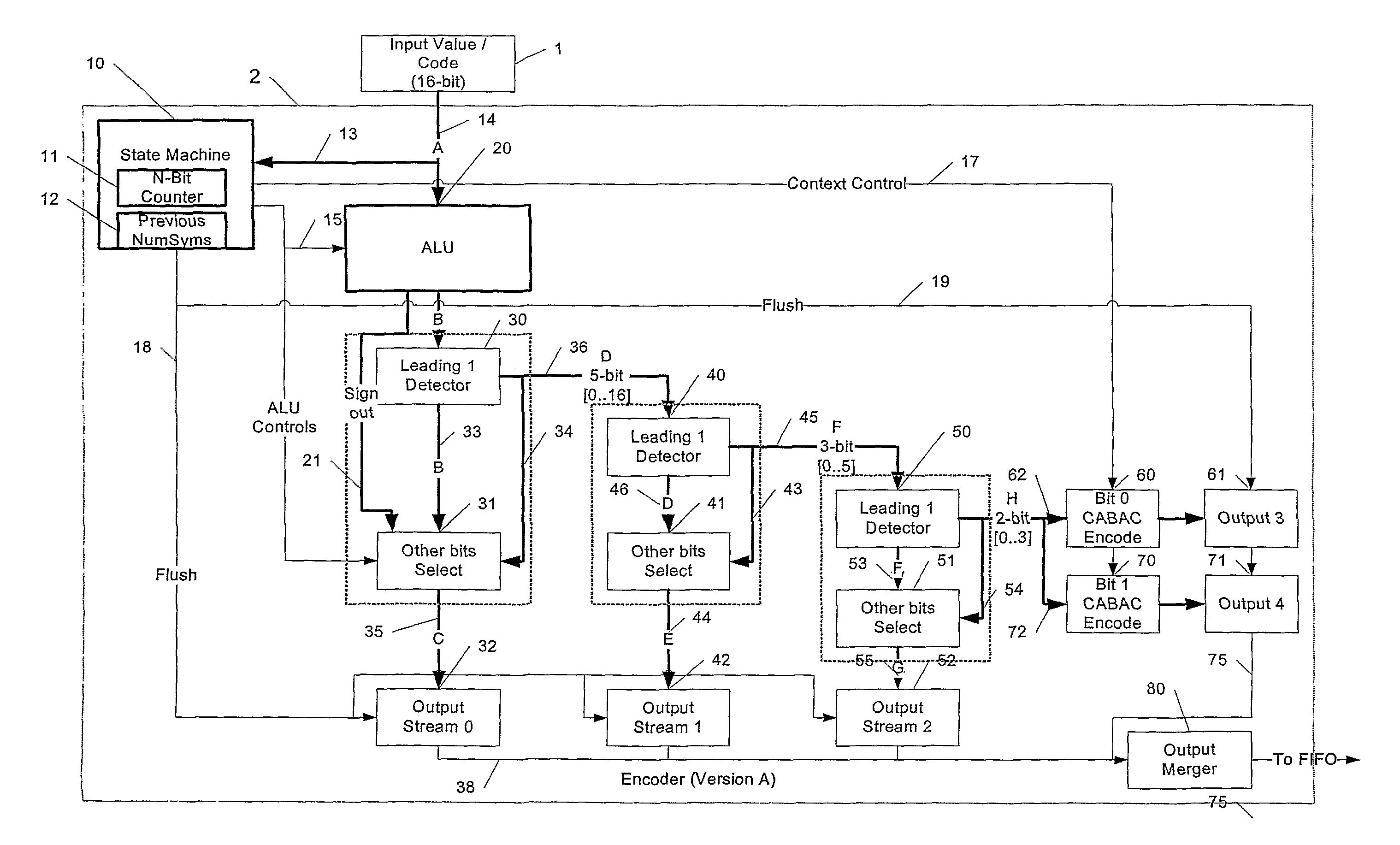
[0043]This application describes a means of compressing and decompressing the FIFO data using arithmetic encoding and decoding that virtually guarantees a rate of one symbol per clock whilst still achieving a respectable compression ratio. It does this through parallelising at least parts of the encode / decode process and in some embodiments by improving the pipelining of the system by decoupling the context selection for a symbol from the previously decoded symbol. In addition, a ‘language syntax’ may be applied on top of the re-encoder-decoder to allow it to be used by multiple parts of the H264 video stream as well as by other video standards—even those employing simpler VLC codes—which can subsequently ease the timing constraints for those decoding units.
[0052]This enables a minimisation of the cost of the encoder / decoder by reducing the number of arithmetic encoders / decoders required.

Problems solved by technology

Such schemes are generally very easy to encode and decode, however, as each code is always an integer number of bits in length, it generally fails to achieve to the optimum described by Shannon.
One drawback, however, is that they are much more complex to encode and decode than a VLC approach.
The H264 CABAC scheme makes the process even more challenging by . . .a) Using the arithmetic encoder / decoder to encode only two symbols, i.e. either 0 or 1, rather than sets of values.
It should be noted, however, that an arithmetic decoder that can decode from a choice of more than two symbols is also more expensive to construct.
There is, however, a cost penalty.
It makes it very difficult, if not impossible, for hardware to decode more than one bit per clock (for a clock rate, say, in the range of 100˜200 Mhz).
If each frame consisted of multiple ‘slices’ (i.e. portions of a frame), then it would be possible to decode each slice in parallel, but as there is no guarantee that the incoming video stream will have more than one slice per frame this is not a suitable approach.
This means that, in the worst case, even if the arithmetic decoder can decode one bit per clock, it may take many clock cycles to obtain the final symbol.
The first may not be possible to achieve with today's technologies and the second is costly to implement.
Therefore, it is likely that an H264 arithmetic decoder hardware solution running at 100˜200 MHz will not achieve one bit per clock which further compounds the timing problems.
It is not difficult to produce a hardware CABAC decoder (say, running at 100˜200 MHz) that can decode a video stream that uses the maximum rate of 50 Mb / s, but a conventional decoder will not produce that data at a steady per-frame rate.
This leads to situations when, very frequently, one unit is stalled by the other due to the mismatch of processing rates.
This, in turn, results in the overall processing rate, in terms of frames per second, dropping to the instantaneous minimum of the two, which could mean the system would fail to meet the required decoding frame rate.
As stated, it is impractical (if not impossible) to make the entropy decoder run faster, and making the consumer units run faster may be exceedingly expensive.
Although a simple FIFO will ‘solve’ the problem, there is the inconvenience that it may need to contain many frames' worth of data in order to effectively smooth the data rate.
This would typically force the buffer to be in external memory which implies not only that it ties up a large amount of RAM but also that it consumes considerable bandwidth for writing and reading of the buffer.
Unfortunately, a likely problem with this method is that it may require a very large window of bits and complicated hardware in order to allow each symbol to be decompressed in a single clock cycle.
The problem is that it an adaptive scheme can be rather sequential to decode and thus makes it difficult to achieve a peak rate of one entire (multi-bit)symbol per clock.

Method used


Image

  • Method of decoding data and apparatus therefor
  • Method of decoding data and apparatus therefor
  • Method of decoding data and apparatus therefor

Examples


Embodiment Construction

[0066]FIG. 1 shows an embodiment of the invention in block schematic form.

[0067]Compressed data is fed to an upstream decoder unit 1. This decoder unit may, for example, be as defined in the H264 video encoding standard. The decoder 1 supplies values which are formatted into an expected syntax and are input to a re-encoder unit 2 as a stream of 16-bit values. The re-encoder 2 compresses these values and outputs the results to a “first in, first out” (FIFO) memory 3. The FIFO 3 may be a set of FIFOs rather than a single FIFO. A decoder unit 4 reads the compressed data from the FIFO 3 and re-expands the data to obtain the original data stream and pass it to an output 5. It will be apparent that there will be a variable time delay between the encoding and decoding of a particular symbol, depending on how much data is maintained in the FIFO 3. An object of the invention is to enable the allocation of a minimum sized FIFO that will prevent pipeline stalls or at least prevent stalls that ...


PUM


Abstract

Incoming decoded data (1), for example from an H264 decoder, is fed to an encoder unit (2) that entropy encodes the decoded data using a parallel encoding scheme that includes context-based arithmetic encoding. The syntax is chosen so that the context does not depend on the immediately previously encoded symbol. The output of the encoder (2) is fed to a FIFO memory whose output is fed to a complimentary decoder (4) whose output produces a delayed copy of the incoming decoded data (1).

Description

FIELD OF THE INVENTION[0001]This invention relates to the processing of entropy encoded data streams, in particular to a method of and apparatus for decoding such data streams.BACKGROUND OF THE INVENTION[0002]Examples of entropy encoded data streams are compressed video data streams including that of the new “H264” video encoding standard (“ITU-T Recommendation H.264: Advanced video coding for generic audiovisual services”). Wiegend et al provide a somewhat shorter summary of this specification in “An Overview of the H.264 / AVC Video Coding Standard” (IEEE Trans. On Circuits and Systems for Video Technology July 2003).[0003]Most video compression schemes include some form of entropy encoding whereby ‘raw’ data symbols are replaced by a representation that reflects their probability of occurrence so that frequently occurring symbols are encoded with a representation with fewer bits, whilst infrequent symbols are encoded with longer representations. Shannon's theory states that the opt...

Claims


Application Information

Patent Timeline
Patent Type & Authority Patents(United States)
IPC IPC(8): H03M7/00
CPCH03M7/4006H04N19/436H04N19/91H04N19/61G06T9/005
Inventor FENNEY, SIMON
Owner IMAGINATION TECH LTD
Learn More