Eureka AIR delivers breakthrough ideas for toughest innovation challenges, trusted by R&D personnel around the world.

Substrate with crystal silicon array

a technology of crystal silicon and substrate, which is applied in the direction of radiation controlled devices, semiconductor/solid-state device details, instruments, etc., can solve the problems of insufficient steady drive current produced by polysilicon tfts formed by ltps technology, the inability to realize sophisticated functions such as central processor unit operations and digital signal processing, and the inability to achieve the effect of organic light-emitting diode displays. rapid thermal breakage of crystalline silicon wafer and rapid mechanical

Inactive Publication Date: 2010-09-07
SHARP KK
View PDF20 Cites 15 Cited by
  • Summary
  • Abstract
  • Description
  • Claims
  • Application Information

AI Technical Summary

Benefits of technology

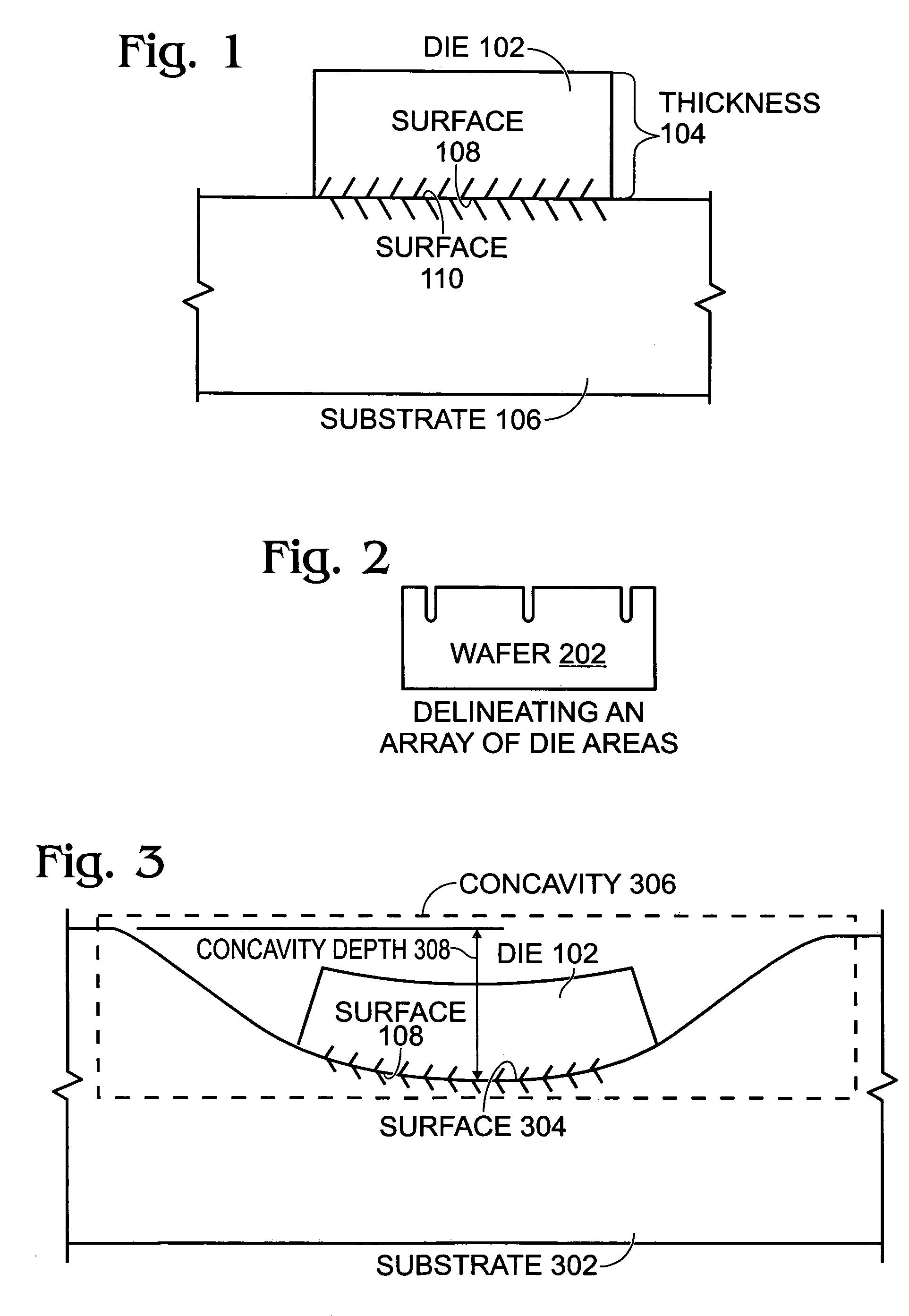
[0011]The present invention describes an array of crystalline silicon dies with thicknesses of 20 nanometers (nm) or more on a substrate with an area of up to two square meters. The present invention also describes a method for yielding the above-mentioned array. The present invention is accomplished using rapid thermal breakage of a crystalline silicon wafer, rapid mechanical placement of the dies on the substrate, and intermolecular bonding of the dies to the substrate. The present invention allows the formation of integrated circuit devices, such as thin film transistors, on transparent or flexible substrates.

Problems solved by technology

Unfortunately, this approach remains relatively expensive for LCD production.
Moreover, polysilicon TFTs formed by LTPS technology may not provide the capability to realize sophisticated functions like central processor unit (CPU) operations and digital signal processing.
Finally, the steadiness of drive currents produced by polysilicon TFTs may be inadequate for organic light emitting diode displays (OLEDs).

Method used


Image

  • Substrate with crystal silicon array
  • Substrate with crystal silicon array
  • Substrate with crystal silicon array

Examples


Embodiment Construction

[0026]The use of single crystal silicon can resolve the thin film transistor and organic light emitting diode display problems noted in the Background Section. Although there currently are techniques for creating films of single crystal silicon on transparent or flexible substrates, there also are problems and limitations associated with these techniques. One such technique is Fluidic-Self-Assembly™ (FSA) by Alien Technology. FSA works best for silicon layers of more than 50 microns. Unfortunately, such blocks constitute a “bulk silicon integrated circuit”, and, consequently, exhibit undesirable capacitive effects that are substantial compared to silicon-on-insulator devices. Also, FSA placement depends on random probability and gravity to move the blocks to their desired locations. As a result, more than 80% of the blocks do not settle in their desired locations and, therefore, need to be recycled or disposed. Thus, FSA placement requires a large number of blocks to populate the de...


PUM


Abstract

An array of crystalline silicon dies on a substrate and a method for yielding the array are provided. The method comprises: delineating an array of die areas on a crystalline semiconductor wafer; implanting the die areas with hydrogen ions; overlying the die areas with a layer of polymer to form, for each die, an aggregate including a die area first wafer layer; polymerically bonding an optically clear carrier to the die areas; thermally annealing the wafer to induce breakage in the wafer; forming, for each die, an aggregate wafer second layer with a thickness less than the die thickness; and, for each die, conformably attaching the aggregate wafer second layer to a substrate. The substrate can have an area of up to approximately two square meters and the wafer second layer can have a thickness of greater than and equal to approximately 20 nanometers.

Description

CROSS REFERENCE TO RELATED APPLICATIONS[0001]This application is a divisional of application Ser. No. 10 / 376,776, filed Feb. 27, 2003 entitled “Crystalline Silicon Die Array and Method for Assembling Crystalline Silicon Sheets Onto Substrates,” invented by Flores et al., now U.S. Pat. No. 6,759,277.BACKGROUND OF THE INVENTION[0002]1. Field of the Invention[0003]This invention generally relates to the fabrication of integrated circuit (IC) devices and, more particularly, to the assembly of thin sheets of single crystal silicon onto substrates.[0004]2. Description of the Related Art[0005]The use of substrate materials other than silicon is of interest, as it would enable the realization of new display products that are not otherwise feasible to make. For example, there is broad agreement in the flat panel display (FPD) industry that system-on-glass (SOG) technology is a natural evolutionary step for FPDs, especially for mobile devices. As an example of this evolution, improvements in ...

Claims


Application Information

Patent Timeline
IPC IPC(8): H01L23/34G02F1/1345H01L21/02H01L21/336H01L21/44H01L21/78H01L23/495H01L27/12H01L27/146H01L29/786
CPCH01L21/7806H01L21/7813H01L27/1469
Inventor FLORES, JAMES S.TAKAFUJI, YUTAKADROES, STEVEN R.
Owner SHARP KK
Why Eureka
Eureka Blog
Learn More