Semiconductor apparatus and method of manufacturing the same
a technology of semiconductor devices and semiconductors, applied in the direction of semiconductor devices, electrical devices, basic electric elements, etc., can solve the problems of difficult formation of amorphous silicon tft and polysilicon, low thermal stability of polysilicon tft,
- Summary
- Abstract
- Description
- Claims
- Application Information
AI Technical Summary
Benefits of technology
Problems solved by technology
Method used
Image
Examples
example 1
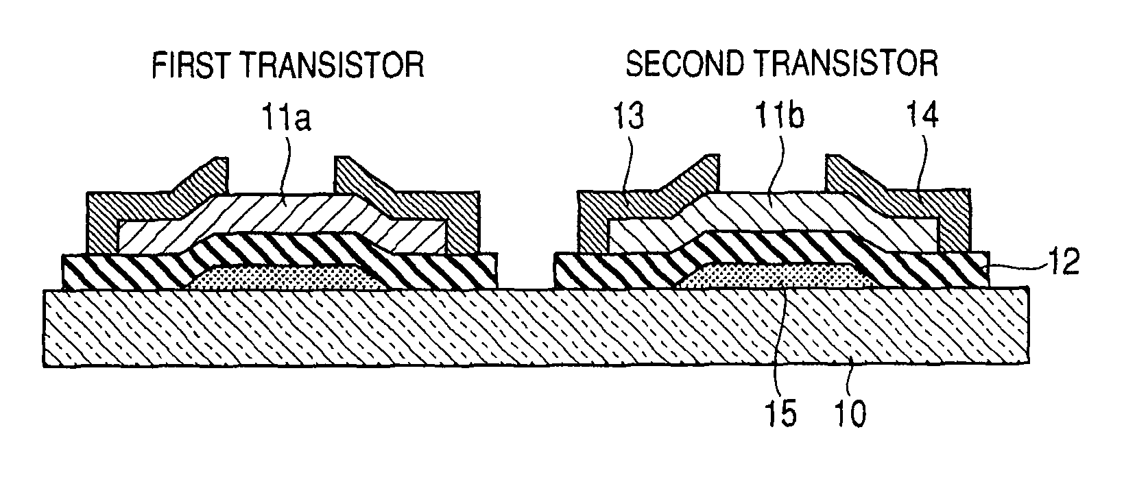
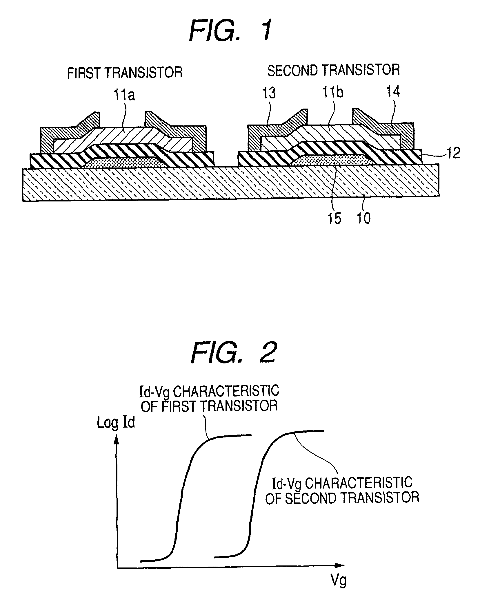
[0158]Example 1 is an example in which a semiconductor apparatus including bottom gate type TFT elements having different threshold voltages was formed on a glass substrate.
[0159]In Example 1, an In—Ga—Zn—O-based amorphous oxide is used for the channel layer 11a and 11b of the transistor. A channel length of the transistor is 60 μm, and a channel width thereof is 180 μm.
[0160]First, on a glass substrate 10 (1737 manufactured by Corning Incorporated), the gate electrode 15 and the gate insulating layer 12 are patterned and formed by a photolithographic method and a lift-off method.
[0161]The gate electrode 15 is formed of a Ta film having a thickness of 50 nm. The gate insulating layer is obtained by forming an SiO2 film by the sputtering method, and has a thickness of 150 nm. In addition, a dielectric constant of the SiO2 film is about 4.6.
[0162]Next, the channel layer of the first transistor was patterned and formed by the photolithographic method and the lift-off method.
[0163]The c...
example 2
[0191]Example 2 is an example of an active matrix circuit substrate on which TFTs having different threshold voltages are arranged in a matrix form.
[0192]In Example 2, an In—Zn—O-based amorphous oxide is used for the channel layers 11a and 11b of the transistor.
[0193]Further, the composition ratio In:Zn of the amorphous oxide is gradually changed in a gate wiring direction of the active matrix.
[0194]As a result, the active matrix circuit substrate having a small gate delay is achieved.
[0195]A method of forming the thin film transistor is based on Example 1, but a thin film with the composition ratio In:Zn gradually changed in the gate wiring direction is formed in the step of forming the channel layer. Further, matrix wirings are separately formed by a general method.
[0196]The channel layer according to Example 2 is formed by using a film formation apparatus having a structure as illustrated in FIG. 9A.
[0197]As illustrated in FIG. 9A, there is employed a method of providing the mate...
example 3
[0219]Example 3 provides an active matrix circuit substrate on which TFTs having different threshold voltages are arranged in a matrix form on a plastic substrate.
[0220]When the active material matrix substrate including oxide semiconductors whose composition ratios are the same is formed on the entire substrate by employment of the method according to Example 1, distribution in device characteristics may be generated depending on the material of the plastic substrate and process conditions.
[0221]For example, when a polyethylene terephthalate (PET) film is used as the substrate, the field effect mobility was smaller at the end portion of the substrate, in some cases, than at the central portion of the substrate (comparative example).
[0222]In forming the channel layer of Example 3, a film formation apparatus having a structure as illustrated in FIG. 10A is used.
[0223]As illustrated in FIG. 10A, there is employed a method of providing the material source A and the material source B to...
PUM
 Abstract
Description
Claims
Application Information
 - R&D
- Intellectual Property
- Life Sciences
- Materials
- Tech Scout
- Unparalleled Data Quality
- Higher Quality Content
- 60% Fewer Hallucinations
Browse by: Latest US Patents, China's latest patents, Technical Efficacy Thesaurus, Application Domain, Technology Topic, Popular Technical Reports.
© 2025 PatSnap. All rights reserved.Legal|Privacy policy|Modern Slavery Act Transparency Statement|Sitemap|About US| Contact US: help@patsnap.com


