
Rotor mechanism of centrifugal compressor

a centrifugal compressor and rotating mechanism technology, applied in mechanical equipment, machines/engines, liquid fuel engines, etc., can solve the problems of low rigidity, low efficiency of hydrodynamic bearings, and inability to teach effective means for blocking contamination of refrigerant loops, etc., to improve compressor efficiency, reduce pressure, and high industrial applicability

Active Publication Date: 2010-09-07
IND TECH RES INST
View PDF8 Cites 7 Cited by
  • Summary
  • Abstract
  • Description
  • Claims
  • Application Information

AI Technical Summary

Benefits of technology

The solution effectively blocks lubricant leakage and refrigerant loss, improves compressor efficiency, and simplifies maintenance by using a more efficient rolling bearing system with labyrinth seals and an oil slinger, reducing contamination and pressure-related issues.

Problems solved by technology

Although U.S. Pat. No. 4,938,664 provides a design for recycling lubricant, it does not teach effective means for blocking contamination of refrigerant loop caused by leakage of lubricants.
Moreover, hydrodynamic bearings are known for poor efficiency, low rigidity, and long time for establishing oil pressure establishing time as mentioned previously.
Surfaces of the hydrodynamic bearings are extremely soft, such that they are extremely likely to be damaged when the compressor comes to a sudden halt.
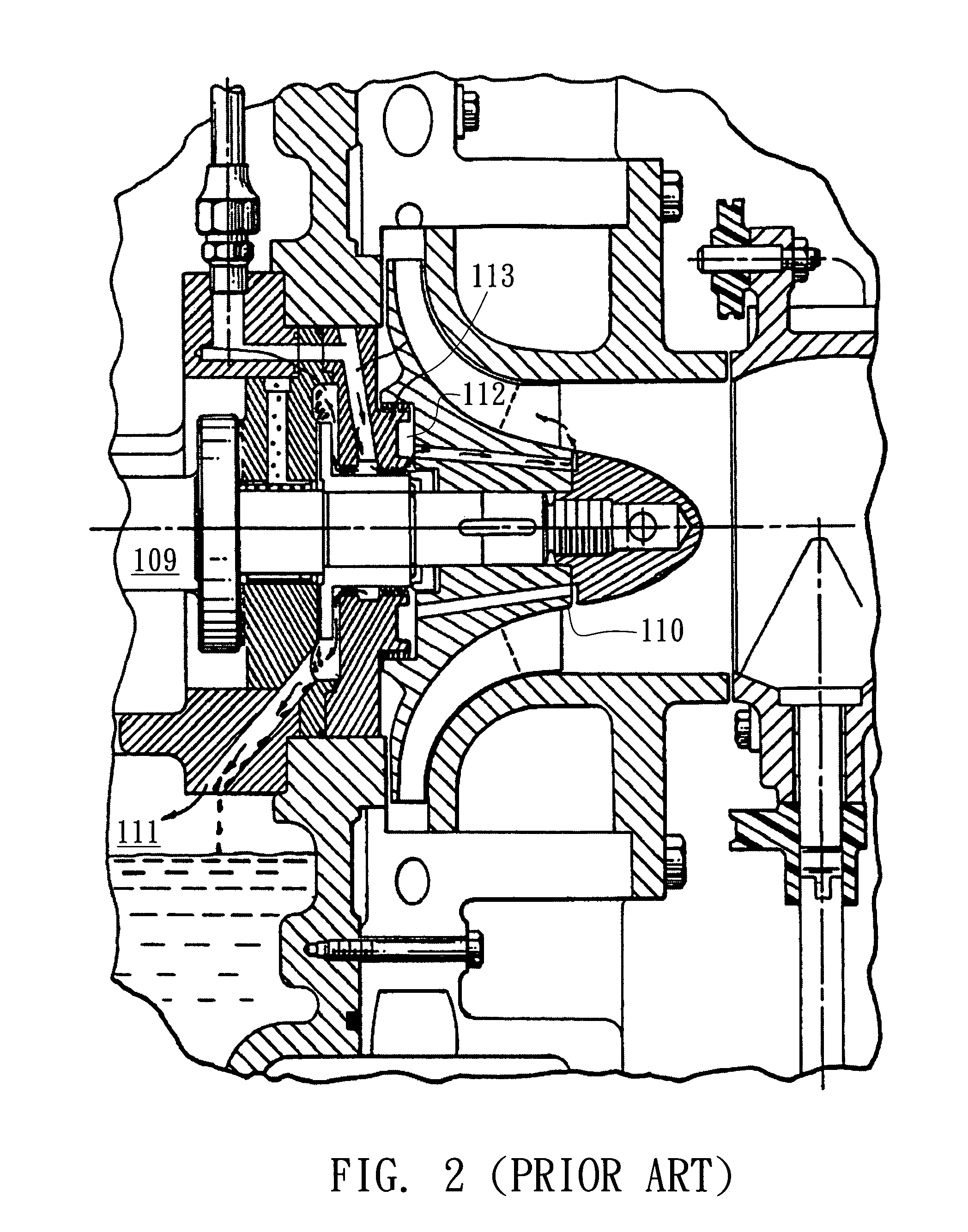
The leakage must therefore be blocked to avoid loss of lubricants, particularly since the hydrodynamic bearings are known for poor efficiency, low rigidity, and long time for establishing oil pressure when actuated, as well as easy damages to the extremely soft surfaces thereof when the compressor comes to a halt suddenly.
After actuation, the high-pressure refrigerant compressed by the impeller 110 may also leak into a lower pressure area along gaps, resulting in a loss of the refrigerant and a decrease in the compressor efficiency.
The two aforesaid patents can provide effective recycling of lubricant for centrifugal compressors, but there are doubts on the efficiency of separation of refrigerants and lubricant sealing.
In particular, it would be a major defect if the leakage of lubricants into the region where the impellor is positioned cannot be blocked.
At the same time, by simply implementing the labyrinth seal cannot ensure insulation, because longer time is required for establishing a pressure and the maintenance of the centrifugal compressor is poor.
Moreover, due to the axial force arisen from a dorsal pressure difference, the use of a single impellor is also likely to cause leakage.

Method used


Image

  • Rotor mechanism of centrifugal compressor
  • Rotor mechanism of centrifugal compressor
  • Rotor mechanism of centrifugal compressor

Examples


Embodiment Construction

[0024]The following embodiments are provided to illustrate the present invention. Persons having ordinary skills in the art can easily appreciate technical feature and the achieved functions of the present invention.

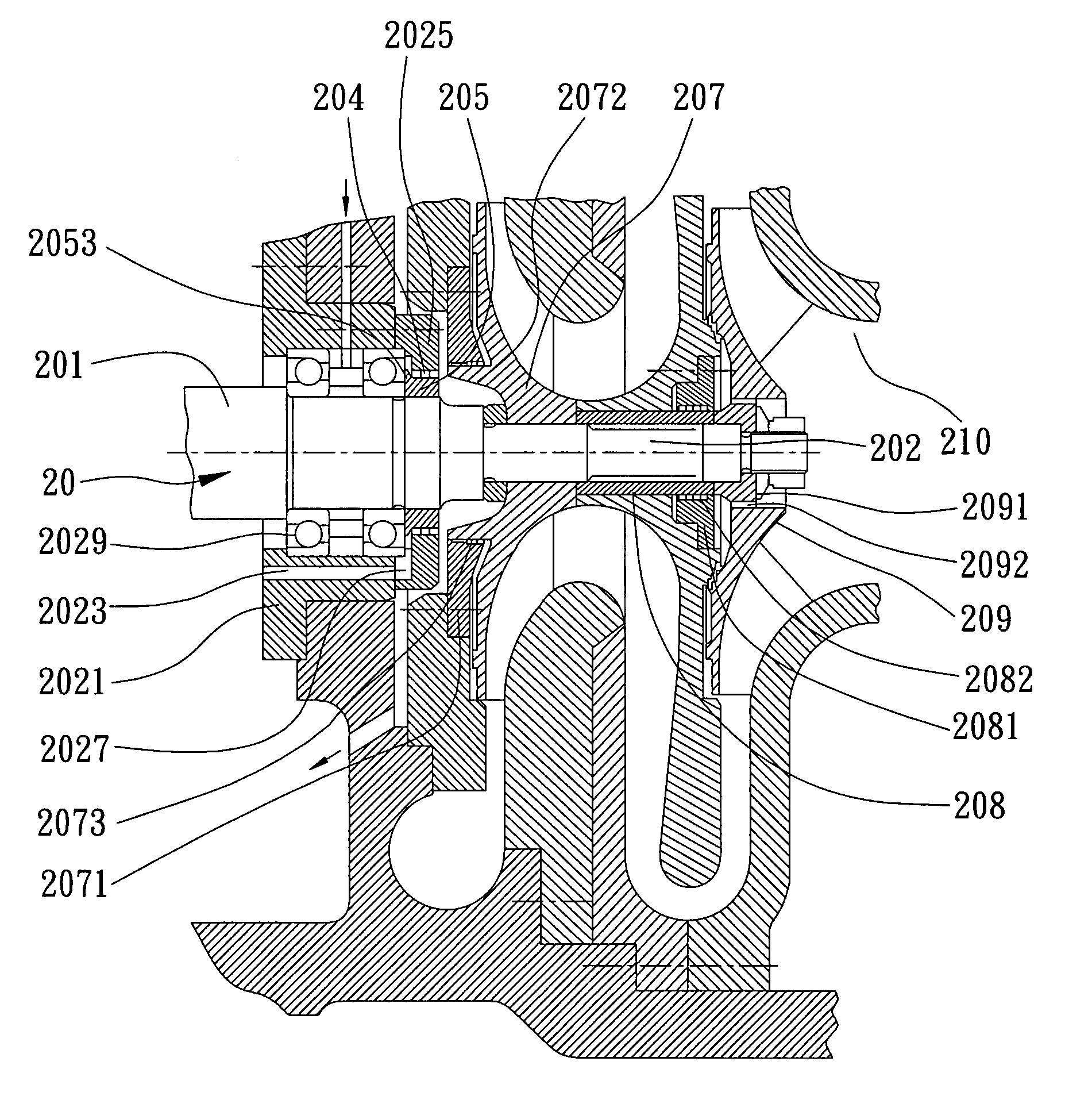
[0025]Referring to FIGS. 3 and 4, the present invention proposes a rotor mechanism of a centrifugal compressor. The rotor mechanism is connectable to a power output device 40, and is used for blocking leakage of lubricants and recycling of lubricants to an oil sump 30. The rotor mechanism comprises a rotary shaft 20, a bearing housing 2021, and a bearing plate 2025. The rotary shaft 20 comprises a drive side 201 and a transmission side 202. A connecting portion 203 connected to the power output device 40, a rolling bearing 2029, and a screw nut 205 for securing are provided in sequence from the drive side 201 to the transmission side 202. The screw nut 205 secures the rolling bearing 2029 in position in the rotary shaft and has an oil slinger 2053 facing the surface of t...


PUM


Abstract

A rotor mechanism of a centrifugal compressor connectable to a power output device and configured to block leakage of lubricants and to recycle lubricants to an oil sump is provided, which includes a rotary shaft with a rolling bearing and a screw nut, a bearing housing for receiving the rolling bearing, and a bearing plate connected to the bearing housing. The screw nut has a surface provided with an oil throw seal, and the bearing housing. As the bearing plate is provided with an oil channel in contact with the oil-returning hole and either one of the bearing housing and the bearing plate is provided with a first labyrinth seal in contact with the screw nut, lubricants leaking out of the rolling bearing is allowed to go to the oil sump via the oil channel and oil-returning hole. The oil slinger thus blocks the lubricants from leaking out of the first labyrinth seal.

Description

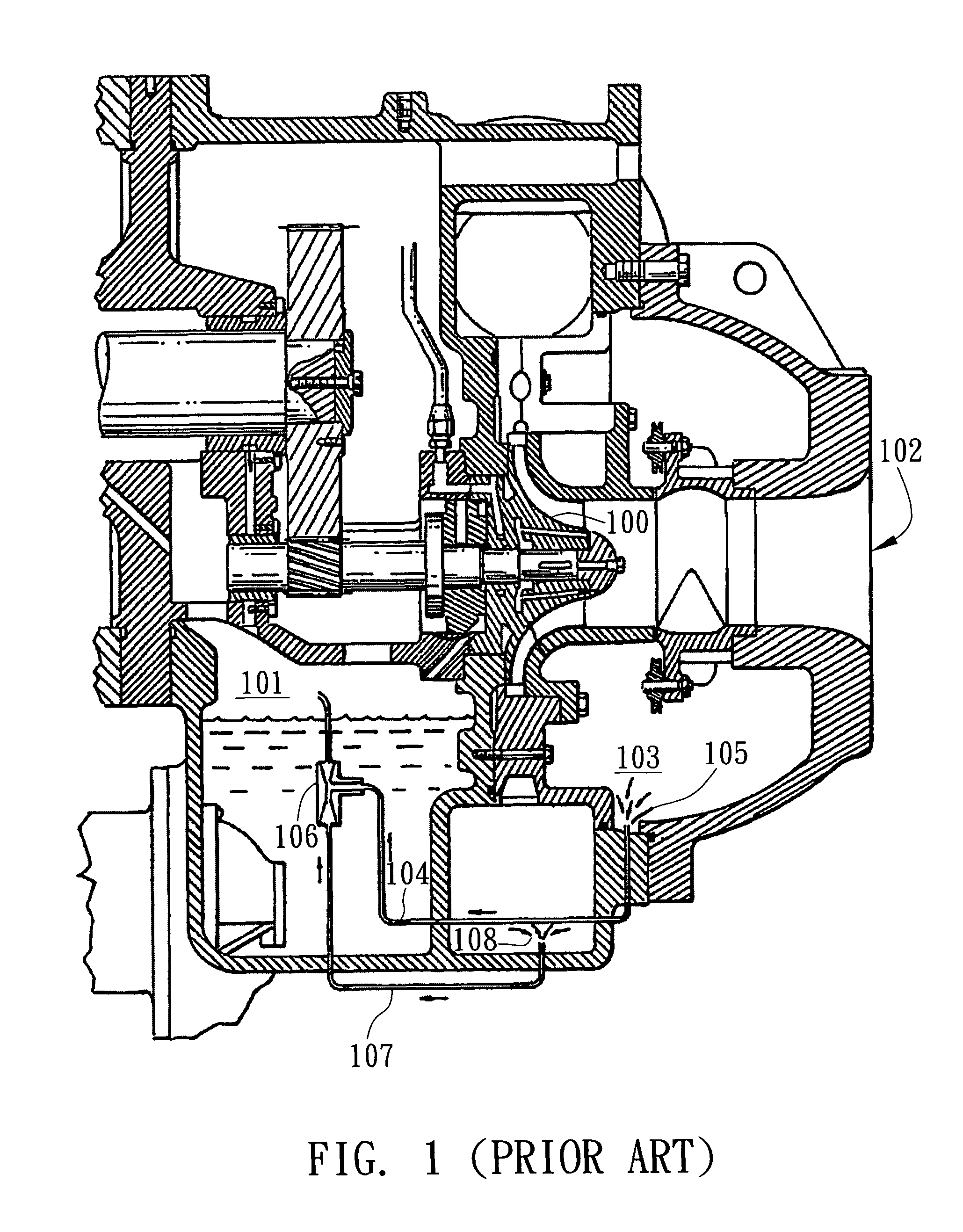
BACKGROUND OF THE INVENTION[0001]1. Field of the Invention[0002]The present invention relates to centrifugal compressors, and more particularly, to a rotor mechanism of a centrifugal compressor for blocking leakage of lubricants and recycling of lubricants.[0003]2. Description of the Prior Art[0004]With continual advancement in compressor technology, requirements for rotational speeds and performance of compressors also increase. As shown in FIG. 1, U.S. Pat. No. 4,938,664 has disclosed an oil reclaim system for use in a centrifugal compressor, wherein a high-pressure refrigerant is used to drive and guide the lubricant to go from an inlet 102 to an oil sump 101 along the lower border of the casing. The refrigerant is rotationally compressed by vanes 100. A jet pump 106 pumps the lubricant to go from an opening 105 to the oil sump 101 via a low-pressure pipe 104. Subjected to the pumping of the jet pump 106, a high-pressure refrigerant gas goes from an opening 108 to the oil sump 10...

Claims


Application Information

Patent Timeline
Patent Type & Authority Patents(United States)
IPC IPC(8): F04D29/06
CPCF04D17/122F04D25/02F04D25/06F04D29/063F04D29/462
Inventor YEN, CHENG-CHUNGCHIANG, CHUNG-PINGCHEN, JIING-FUCHOW, YUNG-LOCHEN, CHUN-HAN
Owner IND TECH RES INST
Learn More