Three-dimensional image display device
a display device and three-dimensional image technology, applied in the field of three-dimensional image display devices, can solve the problems of unstable position of a pixel appearing via an exit pupil when observation is performed from one point at a viewing distance, the difference between the multiview and the ip system, etc., to prevent display blocking and improve the final resolution balance
- Summary
- Abstract
- Description
- Claims
- Application Information
AI Technical Summary
Benefits of technology
Problems solved by technology
Method used
Image
Examples
example 1
[0107]In Example 1, a multiview type three-dimensional image display device with a structure shown in FIG. 19 was manufactured. The two-dimensional image display device 14 was a liquid crystal display device, which was provided at a front face thereof with an optical plate 6 and at a rear face thereof with a back light 16.
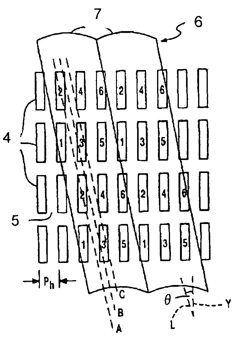
[0108]Specifically, in the example 1, a QUXGA—LCD panel (the number of pixels of 3200×2400 and a screen size of 480 mm×360 mm) was used as the liquid crystal display device. In the liquid crystal display device 14, three pixels of red color, green color, and blue color can be driven independently. A length of each of the pixels of red, green, and blue in a horizontal or lateral direction was 50 μm and a length thereof in a vertical direction was 150 μm. The color filter arrangement was a stripe arrangement. Incidentally, in an ordinary two-dimensional image display device, one pixel (one triplet) is constituted of three sub-pixels of red, green, and blue colors arr...
example 2
[0112]In Example 2, an IP type three-dimensional image display device with the structure shown in FIG. 19 was manufactured. By designing a pitch of an exit pupil of an optical plate to an integral multiple a sub-pixel pitch in the image display device, such a constitution was achieved that a converging point of light rays did not occur in a viewing distance, which was different from the multiview system. Differences between Example 2 and Example 1 will be explained below.
[0113]Design was made that a horizontal pitch of a lens was four times a sub-pixel width, i.e, 600 μm, and a viewing range was ±15° . Thereby, the viewing range (a region could be viewed without mixing a quasi image) corresponding to a screen width at a viewing distance of 1.0 m could be secured. An inclination of a lens was about 14.0°. 28 parallax images whose horizontal directions were applied with parallel projection and whose vertical directions were applied with perspective projection were acquired at the view...
example 3
[0116]Example 3 was approximately similar to the example 2, but it adopted such a design that the standard number of parallaxes was increased to 25. A lenticular lenses designed such that a pixel position on a liquid crystal display panel was a focal length was used as the optical plate. A horizontal pitch of a lens was set to 750 μm which was 15 times a sub-pixel width and an inclination of the lenticular sheet was set to about 11.3°.
[0117]At a viewing distance, 44 parallax images whose horizontal directions and vertical directions were applied with parallel projection were acquired at the viewing distance by setting a target point on a center of a screen and using a camera (a virtual camera in CG). A resolution of the parallax image had a resolution of 640 (×RGB)×480. Mapping of 640×RGB×480×25 parallax information was basically performed according to the mapping shown in FIG. 8. As shown in FIG. 12, column information was maintained by shifting three-dimensional image display pixe...
PUM
| Property | Measurement | Unit |
|---|---|---|
| distance | aaaaa | aaaaa |
| size | aaaaa | aaaaa |
| length | aaaaa | aaaaa |
Abstract
Description
Claims
Application Information
 - Generate Ideas
- Intellectual Property
- Life Sciences
- Materials
- Tech Scout
- Unparalleled Data Quality
- Higher Quality Content
- 60% Fewer Hallucinations
Browse by: Latest US Patents, China's latest patents, Technical Efficacy Thesaurus, Application Domain, Technology Topic, Popular Technical Reports.
© 2025 PatSnap. All rights reserved.Legal|Privacy policy|Modern Slavery Act Transparency Statement|Sitemap|About US| Contact US: help@patsnap.com


