
Yarn feeding plate double-sided floss blowing apparatus for circular knitting machines

a circular knitting machine and blowing machine technology, applied in the direction of textiles and papermaking, knitting, etc., can solve the problems of affecting the quality of fabric, and uneven fabric formation, so as to reduce heat generation, improve the quality of fabric, and increase the li

Inactive Publication Date: 2010-08-31
PAI LUNG MACHINERY MILL CO LTD
View PDF10 Cites 0 Cited by
  • Summary
  • Abstract
  • Description
  • Claims
  • Application Information

AI Technical Summary

Benefits of technology

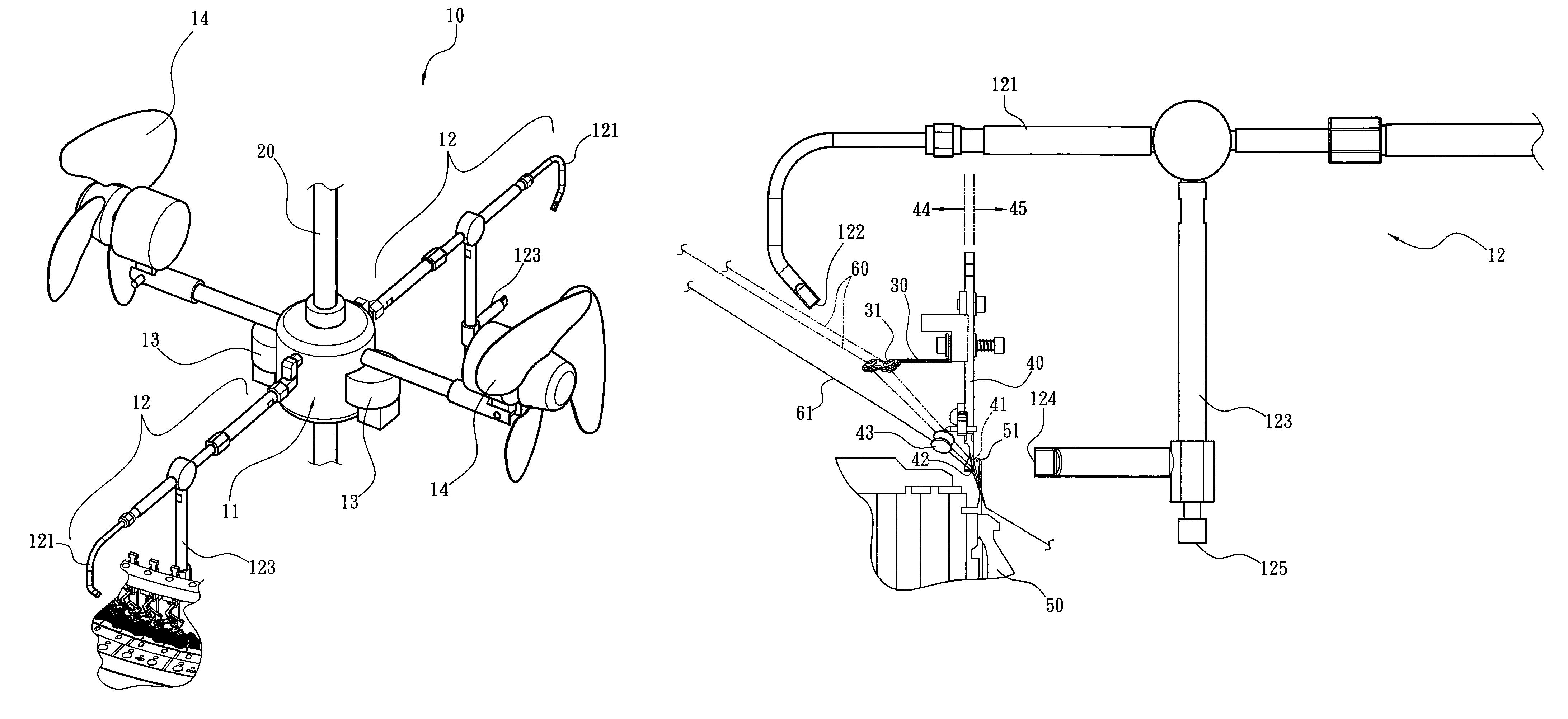
[0004]Therefore, the primary object of the present invention is to overcome the shortcomings of the aforesaid conventional techniques by targeting the lower half portion of outer side and inner side of yarn feeding plates of circular knitting machines that are mostly likely to be adhered and accumulated floss and providing a strong airflow to blow directly and concurrently the inner side and outer side at a shortest distance to render smooth yarn feeding and improve fabric quality knitted by the circular knitting machines without defects, and also reduce heat generated by rotation of the needle cylinder and friction of knitting needles during casting off to increase life span of the needle cylinder and knitting needles.
[0006]By means of the structure set forth above, compared with the conventional techniques, the present invention can achieve the following benefits: 1. the present invention ejects strong airflow through the pressurized air at a shortest distance to directly and concurrently target the inner side and outer side of the lower half portion of the yarn feeding plates that are most likely to be adhered and accumulated floss, namely by positioning the first air ejection nozzle and second air ejection nozzle to directly face the final distal end of the knitting needles before a yarn is picked up for knitting fabric while floss has not yet started accumulating, and ejecting strong airflow at two sides concurrently to blow away the floss, the yarn picked up by the knitting needles does not carry accumulated floss to be knitted the fabric; 2. as the first air ejection nozzle directly ejects the strong airflow at a close distance to blow the outer lower half portion of the yarn feeding plates, a substantial residual airflow is stronger than the conventional one to be skewed to enter the needle cylinder to reduce heat of the needle cylinder and knitting needles.

Problems solved by technology

If the oil sludge is not cleared regularly, the floss accumulates to become cotton balls to hinder forward operation of the yarns, or even be carried with the yarns to be knitted to become the fabric, and the fabric is formed uneven bulged spots and defects thereon that severely affect fabric quality.
In practice, the floss is most likely to accumulate around the yarn feeding apertures at the outer lower half portion of the yarn feeding plates, namely the final distal end where the yarn is picked up by a knitting needle before knitting the fabric, that causes the floss to be carried with the yarn for knitting and affects the fabric quality.
All the aforesaid three conventional techniques, due to their structural and design constraints, do not provide direct floss blowing structure or function to target the outer lower half portion of the yarn feeding plates from outside towards inside.
Hence they fail to target the outer lower half portion of the yarn feeding plates where the floss is most likely to be accumulated to provide most direct floss blowing at the shortest distance from the outside towards the inside.
As a result, the accumulated floss often is carried with the yarn picked up by the knitting needle for knitting fabric and creates detects of uneven bulged spots on the fabric that severely affect the fabric quality.

Method used


Image

  • Yarn feeding plate double-sided floss blowing apparatus for circular knitting machines
  • Yarn feeding plate double-sided floss blowing apparatus for circular knitting machines
  • Yarn feeding plate double-sided floss blowing apparatus for circular knitting machines

Examples


Embodiment Construction

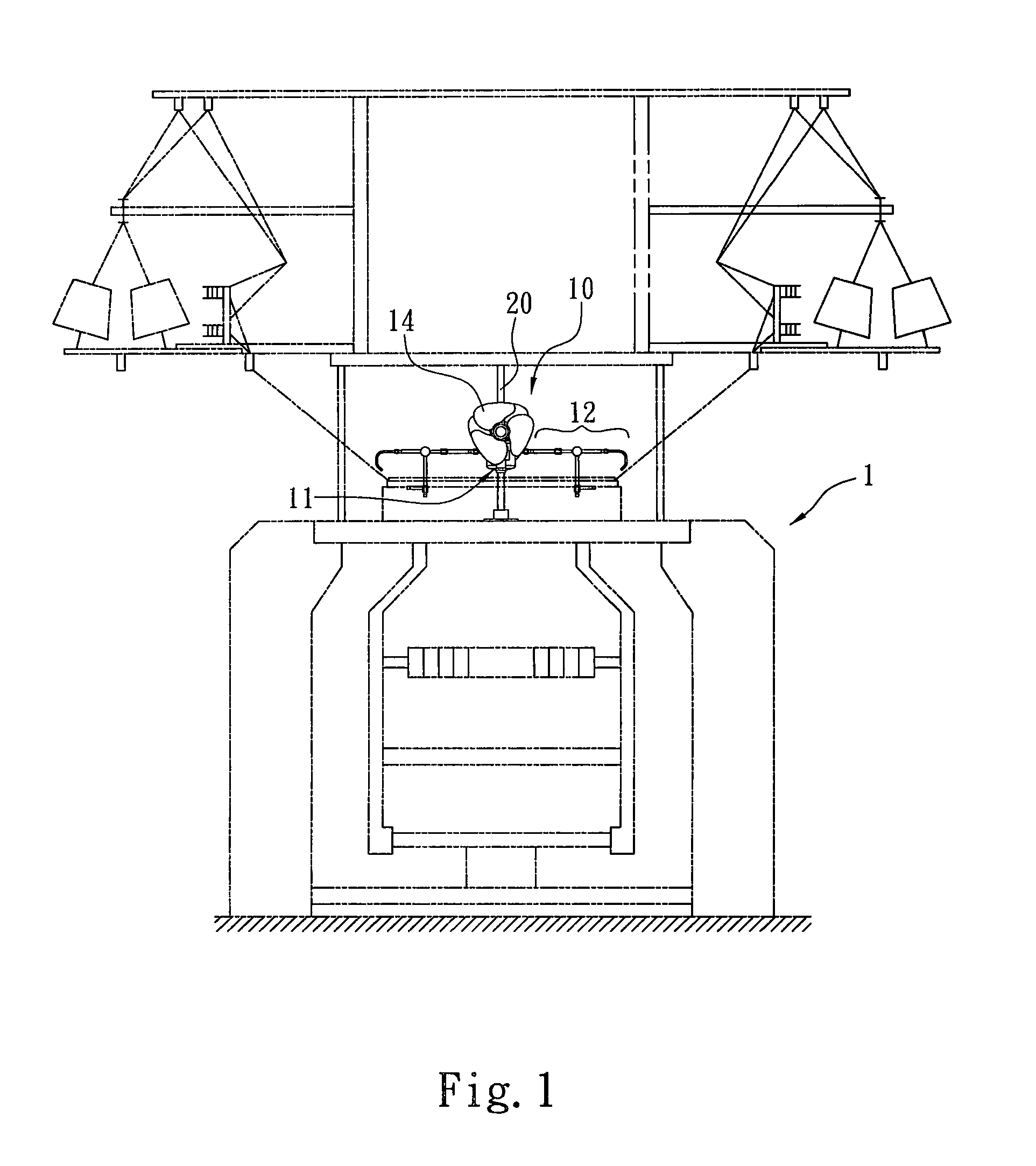
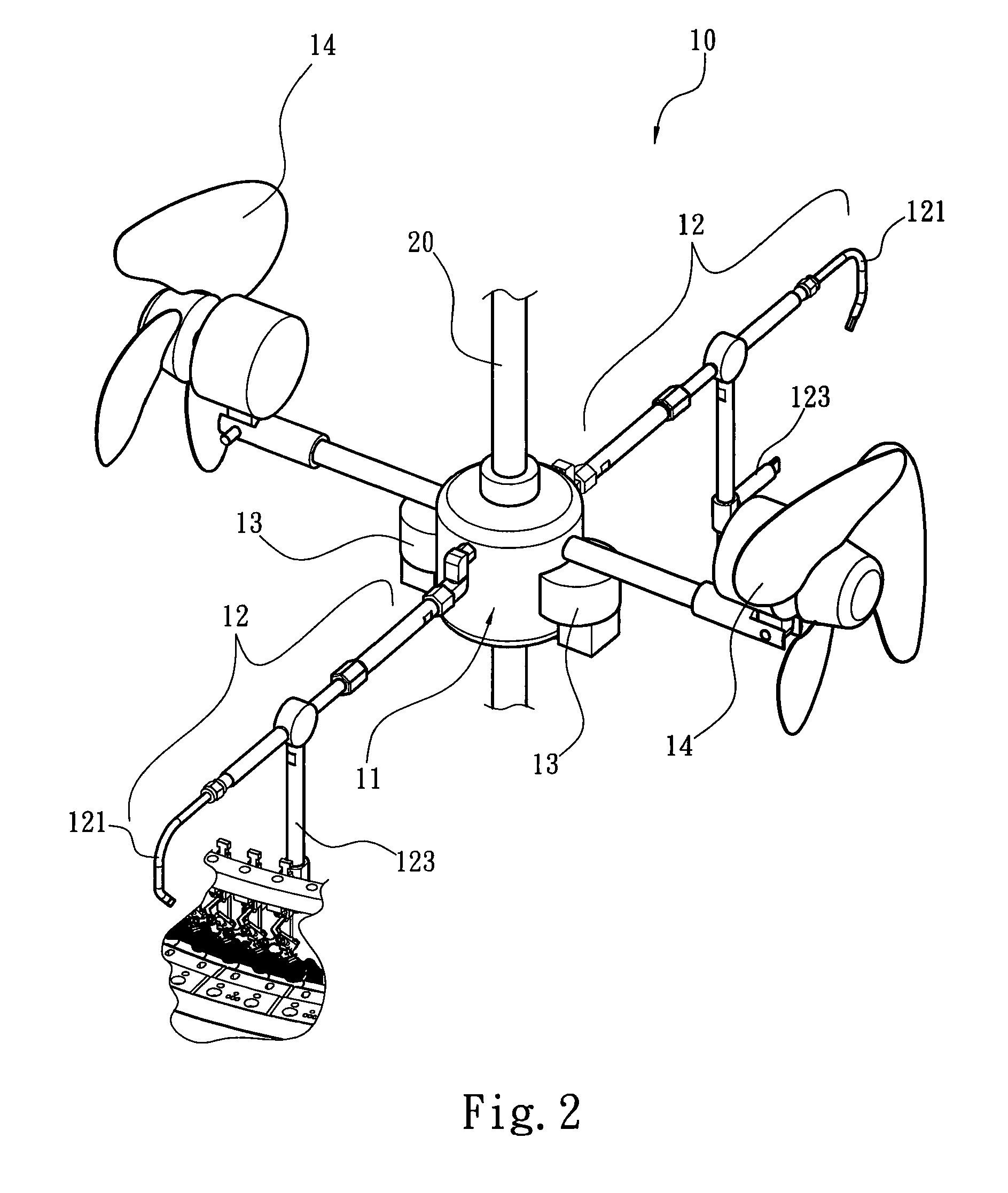
[0013]Please refer to FIGS. 1 through 4 for an embodiment of the yarn feeding plate double-sided floss blowing apparatus for circular knitting machines of the present invention. The present invention provides a floss blowing apparatus 10 axially located in a circular knitting machine 1. The circular knitting machine 1 includes a needle cylinder 50 located annularly thereof which holds a plurality of knitting needles 51, a plurality of yarn guiding apertures 31 and horizontal yarn guiding blades 30 that are located annularly above the needle cylinder 50, and a plurality of vertical yarn feeding plates 40. Each yarn feeding plate 40 has an outer side 44 with a yarn feeding trench 42 formed at the bottom edge of the lower half portion thereof. The lower half portion of the outer side 44 close to the upper side of the yarn feeding trench 42 has at least one yarn feeding aperture 41 running through an inner side 45 of the yarn feeding plate 40. The floss blowing apparatus 10 further incl...


PUM


Abstract

A yarn feeding plate double-sided floss blowing apparatus for circular knitting machines is installed in a circular knitting machine which includes a needle cylinder to hold a plurality of knitting needles and yarn feeding plates. The floss blowing apparatus comprises an air blowing unit. The air blowing unit includes a first air blowing duct and a second air blowing duct. The first air blowing duct has one end extended above the yarn feeding plates and bent towards a lower half portion of an outer side of the yarn feeding plates to form a first air ejection nozzle. The second air blowing duct has one end extended close to a lower half portion of an inner side of the yarn feeding plates and above the knitting needles to form a second air ejection nozzle. Thus strong airflow can blow away the floss on the yarn feeding plates at the shortest distance.

Description

FIELD OF THE INVENTION[0001]The present invention relates to a floss blowing apparatus and particularly to a floss blowing apparatus for circular knitting machines.BACKGROUND OF THE INVENTION[0002]During fabric knitting operation of a conventional circular knitting machine, feeding yarns have to be stretched tightly to enhance smooth of the knitting operation. The yarns have to go through various types of motions such as removing, guiding and feeding that incur friction with yarn guiding blades or yarn feeding plates and generate a lot of loose floss. As knitting elements of the circular knitting machine are automatically and regularly sprayed with lubricant or coolant during knitting operation, the fast spinning needle cylinder tends to hit the lubricant or coolant to generate foam type oil sludge adhered to the yarn feeding plates. The dropping floss easily adheres to the smeared yarn feeding plates. If the oil sludge is not cleared regularly, the floss accumulates to become cotto...

Claims


Application Information

Patent Timeline
Patent Type & Authority Patents(United States)
IPC IPC(8): D04B35/32
CPCD04B35/32
Inventor CHEN, SHIH-CHI
Owner PAI LUNG MACHINERY MILL CO LTD
Learn More