
A purely pneumatic folding-in device for short raw edges of a shuttleless loom

A technology of tuck-in edge device and shuttleless loom, which is applied in looms, textiles, textiles and papermaking, etc. It can solve the problems of unstable mechanical parts, affecting production efficiency, and long burr length, so as to improve production efficiency and fabric High quality, high performance-price ratio, reasonable design effect

Active Publication Date: 2016-04-13
TONGXIANG BEITE TECH CO LTD
View PDF7 Cites 0 Cited by
  • Summary
  • Abstract
  • Description
  • Claims
  • Application Information

AI Technical Summary

Problems solved by technology

[0002] The development and application of shuttleless looms such as rapier looms, air-jet looms, and projectile looms has brought the output of the textile industry to a new level. Among them, popular shuttleless looms are popular among small and medium-sized enterprises because of their low price. However, due to the structural characteristics of the weft insertion mechanism during the weaving process, the popular shuttleless looms have raw edges and cannot form natural weft yarns into the selvedges during the weft insertion process like shuttle looms. While affecting the textile effect, post-processing such as cutting, hemming, and sewing is required, which not only takes a lot of time and labor, but also wastes a lot of raw materials, which greatly increases the production cost of textile enterprises.
In order to achieve the smooth edge requirements of fabrics, mechanical tuck-in devices or pneumatic and mechanical tuck-in devices are added to some shuttleless looms, which are only suitable for low-speed looms due to the instability of the mechanical parts. Moreover, the mechanism is easily damaged, the weft insertion rate is low, and the length of the burrs that can be folded in is too long, etc., which greatly affect the production efficiency.

Method used


Image

  • A purely pneumatic folding-in device for short raw edges of a shuttleless loom
  • A purely pneumatic folding-in device for short raw edges of a shuttleless loom
  • A purely pneumatic folding-in device for short raw edges of a shuttleless loom

Examples


Embodiment Construction

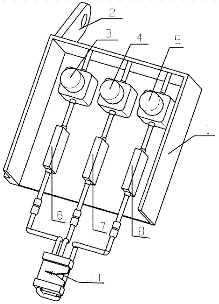
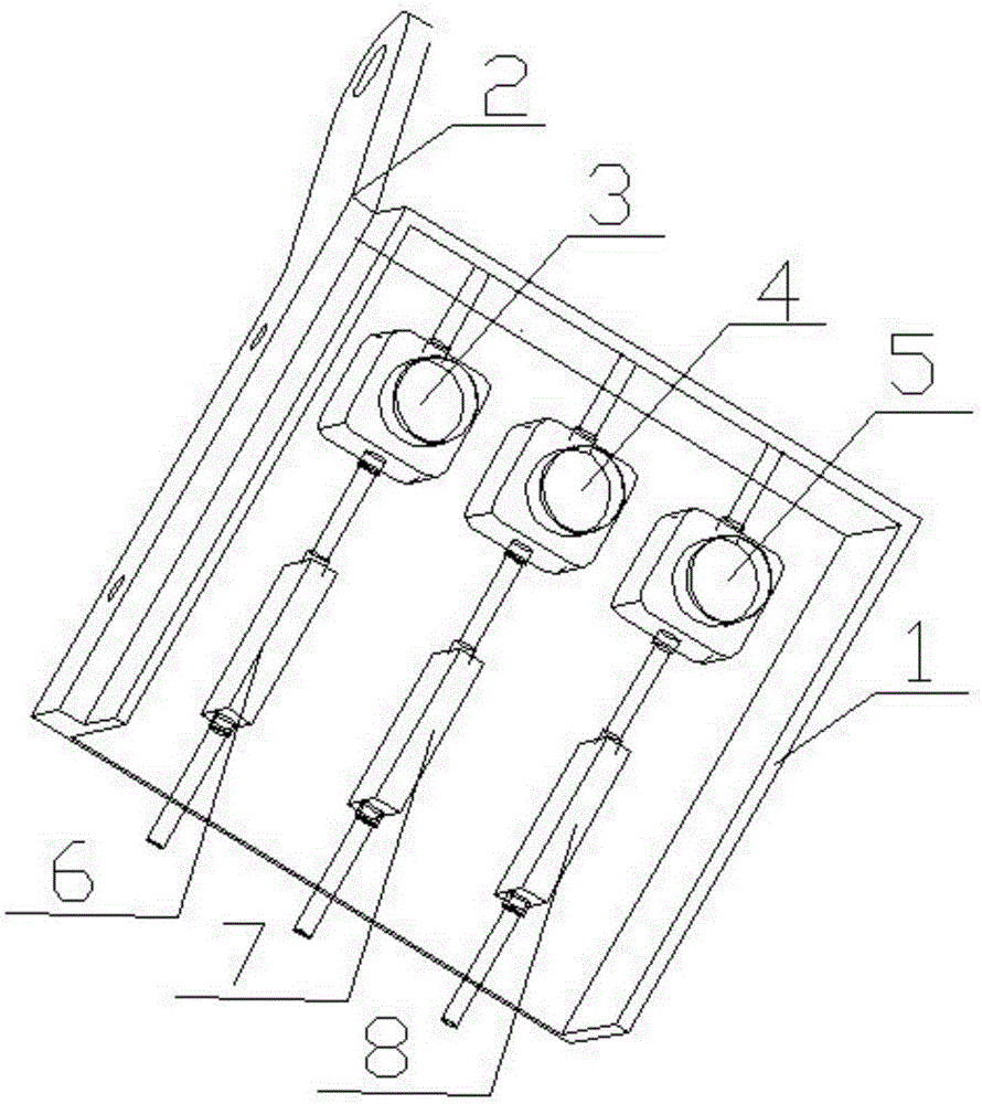
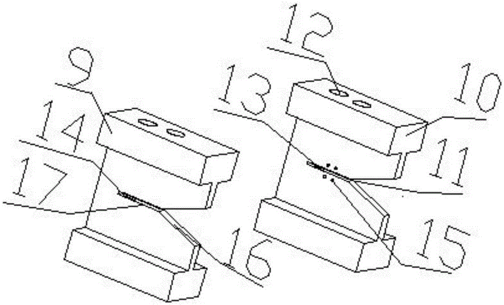
[0012] A kind of pure pneumatic folding-in device for the short raw edge of the shuttleless loom in this embodiment, such as Figure 1-3 As shown, it includes a symmetrically arranged left purely pneumatic fold-in device 9, a right purely pneumatic fold-in device 10, and two control boxes 1, and one of the two control boxes 1 is connected with the left purely pneumatic fold-in device through a pipeline. The edge entering device 9 is connected, and the other is connected with the right pure pneumatic folding device 10 through a pipeline. The left pure pneumatic folding device 9 and the right pure pneumatic folding device 10 are respectively installed on the shuttleless loom close to On the frame on both sides of the weaving fell; the left pure pneumatic folding device 9 and the right pure pneumatic folding device 10 are respectively provided with a Y-shaped yarn guide port 11 and a round yarn end Holding through hole 12, 1 lower yarn end rectangular narrow and long holding thro...


PUM


Abstract

The invention discloses a purely pneumatic tuck-in device for a short burr of a shuttleless loom, which comprises a symmetrically arranged left purely pneumatic tuck-in device, a right purely pneumatic tuck-in device and two control boxes, and the two One of the control boxes is connected to the left purely pneumatic tuck-in device through a pipeline, and the other is connected to the right purely pneumatic tuck-in device through a pipeline. The left purely pneumatic tuck-in device and the right purely pneumatic tuck-in device are They are respectively installed on the frame near the two sides of the weaving mouth on the shuttleless loom; the left pure pneumatic tuck-in device and the right pure pneumatic tuck-in device are respectively provided with a Y-shaped yarn guide port and 2 Circular holding holes at the upper yarn end, 2 rectangular narrow and long holding holes at the lower yarn end, 1 oblique blowing hole at the yarn end and 4 fold-in holes at the yarn end. The invention has the characteristics of reasonable design, compact structure, high performance and price ratio, and can better realize burrs folded in 5-8mm, thereby improving production efficiency and fabric quality.

Description

technical field [0001] The invention relates to a burr processing device on a shuttleless loom, in particular to a purely pneumatic folding-in device for short burrs of a shuttleless loom. Background technique [0002] The development and application of shuttleless looms such as rapier looms, air-jet looms, and projectile looms has brought the output of the textile industry to a new level. Among them, popular shuttleless looms are popular among small and medium-sized enterprises because of their low price However, due to the structural characteristics of the weft insertion mechanism during the weaving process, the popular shuttleless looms have raw edges and cannot form natural weft yarns into the selvedges during the weft insertion process like shuttle looms. While affecting the textile effect, post-processing such as cutting, hemming, and sewing is required, which not only takes a lot of time and labor, but also wastes a lot of raw materials, which greatly increases the pr...

Claims


Application Information

Patent Timeline
Patent Type & Authority Patents(China)
IPC IPC(8): D03D47/40
CPCD03D47/48
Inventor 刘宜胜胡旭东包西平
Owner TONGXIANG BEITE TECH CO LTD
Learn More