
Fabric pull-down devices for computerized flat knitting machine

A computerized flat knitting and fabric technology, applied in the directions of knitting, weft knitting, textiles and papermaking, can solve the problems of unstable tension and uneven tension, and achieve the effect of high fabric quality

Pending Publication Date: 2020-03-27
桐乡市强隆机械有限公司
View PDF1 Cites 0 Cited by
  • Summary
  • Abstract
  • Description
  • Claims
  • Application Information

AI Technical Summary

Problems solved by technology

[0002] The fabric pull-down device is used to pull down the braided fabric that hangs down from the tooth mouth formed between the front needle bed and the rear needle bed of the flat knitting machine. For example, a patent for a braided fabric is disclosed in a patent with the authorization notification number CN106192187B , the catch and pull-down mechanism in the pull-down device uses the method of driving the pull-down triangular shaft to rotate in a specific direction to drive the catch member to move up and down and then pull down the fabric, which belongs to the rotating roller method, but the pulling force generated by the rotating roller method is unstable. Disadvantages, for example, when weaving pieces of cloth on the front and rear needle beds respectively, the pulling force of the rotating roller will be affected by the sliding friction between the pieces of cloth, and the pulling force will be uneven to make pieces of different lengths. Therefore, it is necessary to improve and improve the existing pull-down device. optimization

Method used


Image

  • Fabric pull-down devices for computerized flat knitting machine
  • Fabric pull-down devices for computerized flat knitting machine
  • Fabric pull-down devices for computerized flat knitting machine

Examples


Embodiment 1

[0030] see Figure 1 to Figure 7 .

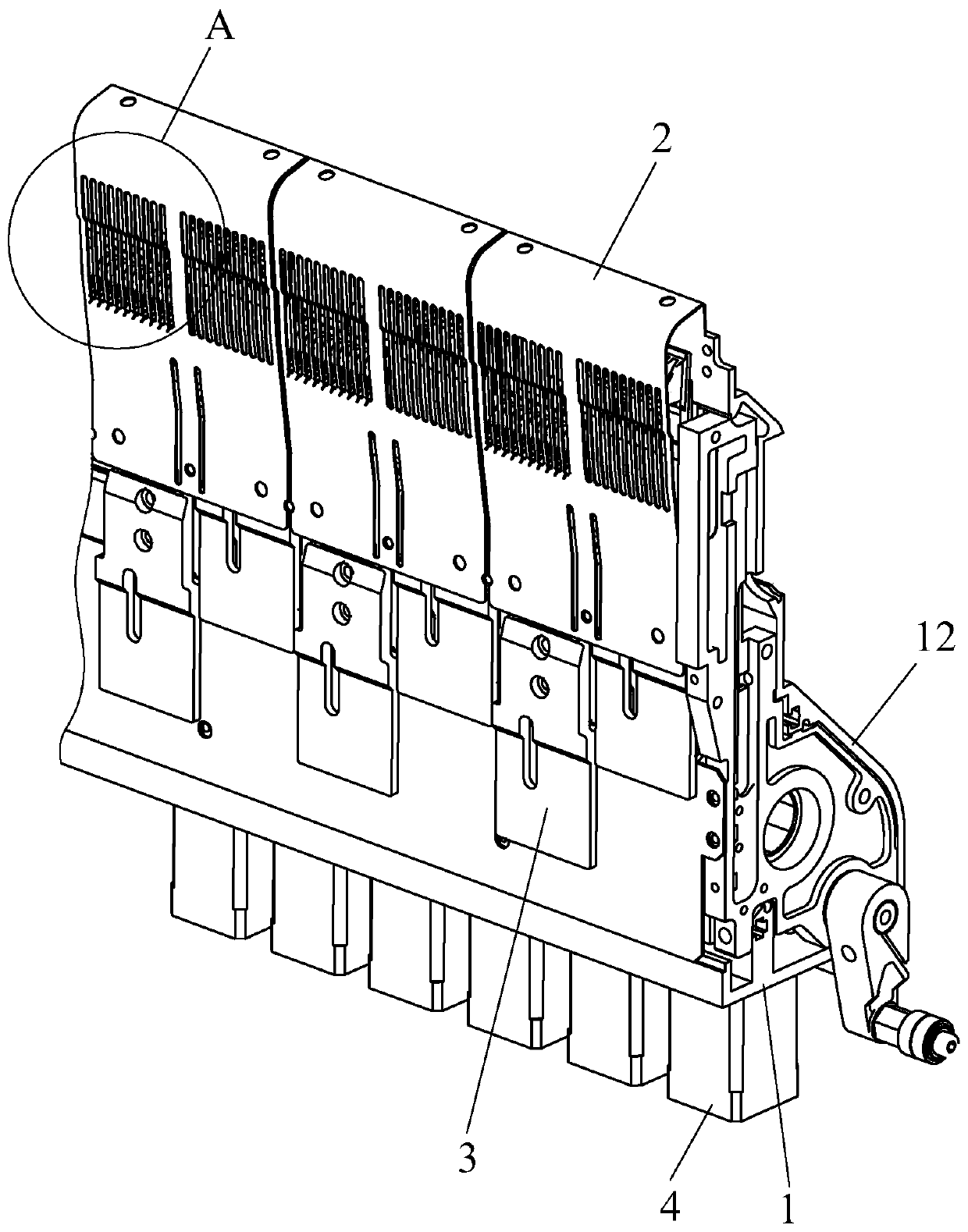
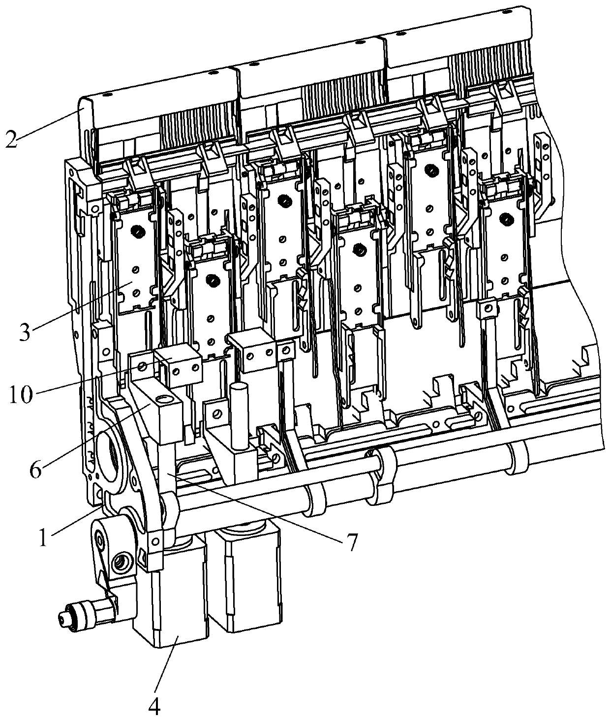
[0031] This embodiment discloses a fabric pull-down device for computerized flat knitting machines, which are arranged in pairs under the front and rear needle beds of the flat knitting machine. The fabric pull-down device includes a base 1, an upper shield 2, several Catch pawl 3 and be used to drive the drive motor 4 that catches paw 3 to move up and down, and drive motor 4 adopts servo motor.

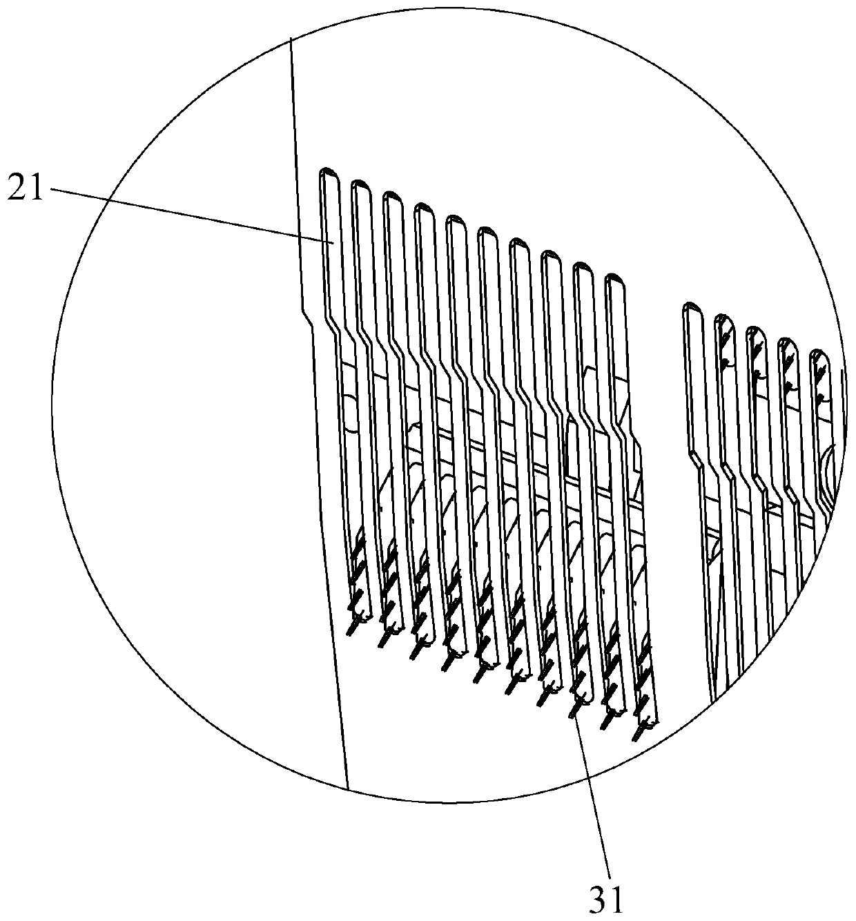
[0032] In this embodiment, the catch claw 3 is provided with a needle 31 for hooking the fabric, and the base 1 is fixedly installed on the flat knitting machine. The upper shield 2 is installed above the base 1, and its front side is provided with a slot 21 that can expose the needle 31 on the catch claw 3.

[0033] In this embodiment, a catch claw 3 is equipped with a drive motor 4, and the drive motor 4 is installed on the base 1. When the drive motor 4 drives the catch claw 3 to descend, the catch claw 3 approaches the front side of the uppe...

Embodiment 2

[0040] refer to Figure 8 to Figure 10, the difference between the present embodiment 2 and the embodiment 1 is: a push rod 9 is equipped with a push rod electromagnet 11, and the push rod electromagnet 11 is installed on the base 1, and it acts on the tail of the rise rod 9 to catch the paw 3 When rising to a certain height, the push rod of the push rod electromagnet 11 stretches out against the tail of the warping rod 9, so that the tail of the warping rod 9 moves toward the front side of the upper shield 2, that is, drives the catch claw 3 Turn away from the direction of the front side of the upper shield 2, so that the catch claws 3 are completely in the upper shield 2.


PUM


Abstract

The invention relates to fabric pull-down devices for a computerized flat knitting machine. The fabric pull-down devices are arranged below a front needle bed and a rear needle bed of the flat knitting machine in pairs, needles used for hooking the fabric are arranged on catch claws, and a base is fixedly installed on the flat knitting machine; an upper shield is mounted above the base, and slot holes capable of exposing the needles on the catch claws are formed in the front side face of the upper shield; and one catch claw is provided with a drive motor, the drive motor is mounted on the base, and in the process that the drive motors drive the catch claws to descend, the catch claws are inclined towards the front side close to the upper shield and the needles used for hooking the fabric are exposed from the slot holes. Each catch claw is provided with a driving motor for individual control, and lifting of the catch claws can be set according to the characteristics of the fabric, so that the quality of the fabric is higher; the tension of the pull-down devices is more stable than that of a common rotating roller, and when the front and rear needle beds are respectively used for knitting cloth pieces, the pull-down devices pull the front and rear pieces of cloth downwards to make the tension of the two pieces of cloth to be the same.

Description

technical field [0001] The invention relates to the field of computerized flat knitting machines, in particular to a fabric pull-down device for computerized flat knitting machines. Background technique [0002] The fabric pull-down device is used to pull down the braided fabric that hangs down from the tooth mouth formed between the front needle bed and the rear needle bed of the flat knitting machine. For example, a patent for a braided fabric is disclosed in a patent with the authorization notification number CN106192187B , the catch and pull-down mechanism in the pull-down device uses the method of driving the pull-down triangular shaft to rotate in a specific direction to drive the catch member to move up and down and then pull down the fabric, which belongs to the rotating roller method, but the pulling force generated by the rotating roller method is unstable. Disadvantages, for example, when weaving pieces of cloth on the front and rear needle beds respectively, the ...

Claims


Application Information

Patent Timeline
IPC IPC(8): D04B15/90
CPCD04B15/90
Inventor 钟佳明安勇强俞惠钟张锋韩徐斌王靖敏
Owner 桐乡市强隆机械有限公司
Learn More