
Unitary cosmetic compact with decoupled motion

a compact device and compact technology, applied in the direction of packaging foodstuffs, packaging goods, transportation and packaging, etc., can solve the problems of cosmetic articles and carriers that the cap is not movable, and the cosmetic article and the carrier cannot move with respect to the base, so as to achieve the effect of increasing stability

Active Publication Date: 2010-08-24
ELC MANAGEMENT LLC
View PDF79 Cites 11 Cited by
  • Summary
  • Abstract
  • Description
  • Claims
  • Application Information

AI Technical Summary

Benefits of technology

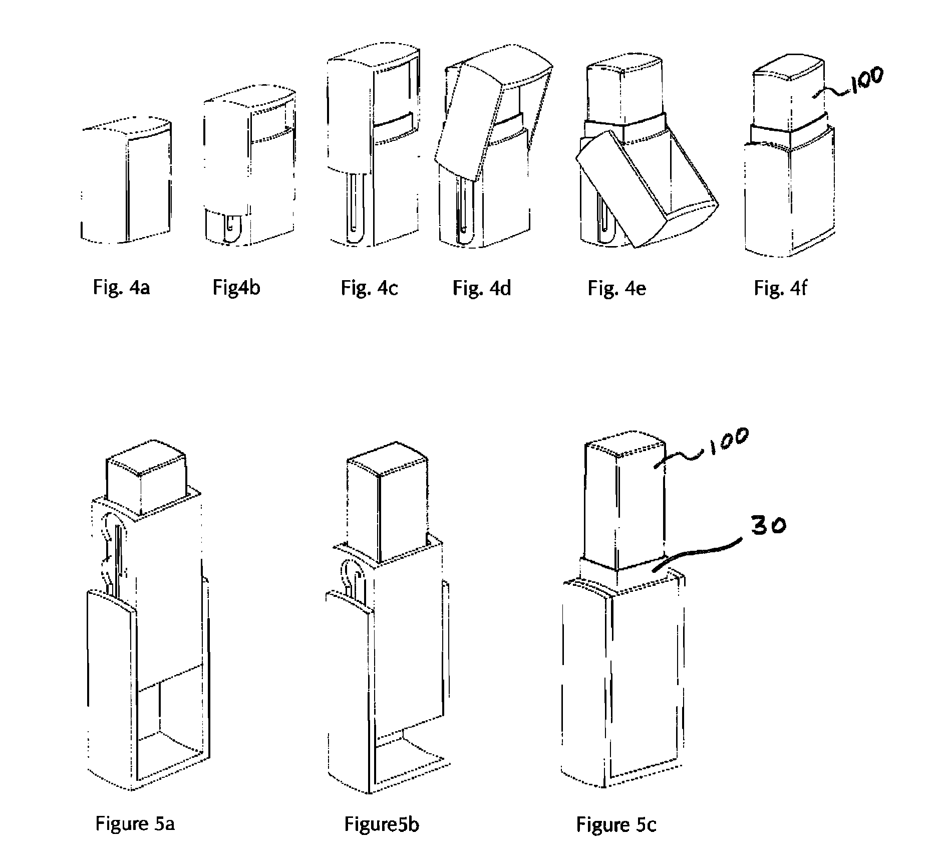
[0011]The present invention is a convenient-to-use, unitary cosmetic compact of increased stability, comprising a base, a cosmetic article carrier disposed within the base and a cap. With respect to the base, the cap is sometimes capable of translational movement and sometimes capable of rotational movement, but the cap can only perform one type of motion at a time. Furthermore, the user does not have a choice, in that, the type of movement (translation or rotation) that the cap may execute is dictated by the relative orientation of the cap and base. There is one exception to this rule. There is exactly one orientation of the cap with respect to the base from which the user has a choice to execute either translation or rotation, but not both simultaneously. In any other orientation, the cap has only one type of movement available to it. At all times, translation of the cap with respect to the base causes translation of the cosmetic article carrier, either toward the bottom or toward the top of the base. Rotation of the cap with respect to the base does not affect the position of the cosmetic article carrier.
[0012]Preferably, the cap is capable of rotating at least 180°. The present invention is unique, in part, because the translational (or vertical) motion of the cap is decoupled from the rotational (or pivoting) motion of the cap. Put another way, compound movement of the cap, with respect to the base, is not possible. “Compound movement” means two or more types of motion occurring simultaneously, i.e. translation and rotation. Furthermore, when pressure is applied to the cosmetic article (during use, for example) the cosmetic article and carrier cannot move with respect to the base. Inadvertent movement of the carrier is eliminated because, when the device is in an orientation for use, translational movement of the carrier is prohibited. These features create greater stability during use. The user is less likely to fumble with the device or have the device move inadvertently during use. The device may be operated with one fluid motion by the user.

Problems solved by technology

Put another way, compound movement of the cap, with respect to the base, is not possible.
Furthermore, when pressure is applied to the cosmetic article (during use, for example) the cosmetic article and carrier cannot move with respect to the base.

Method used


Image

  • Unitary cosmetic compact with decoupled motion
  • Unitary cosmetic compact with decoupled motion
  • Unitary cosmetic compact with decoupled motion

Examples


example 1

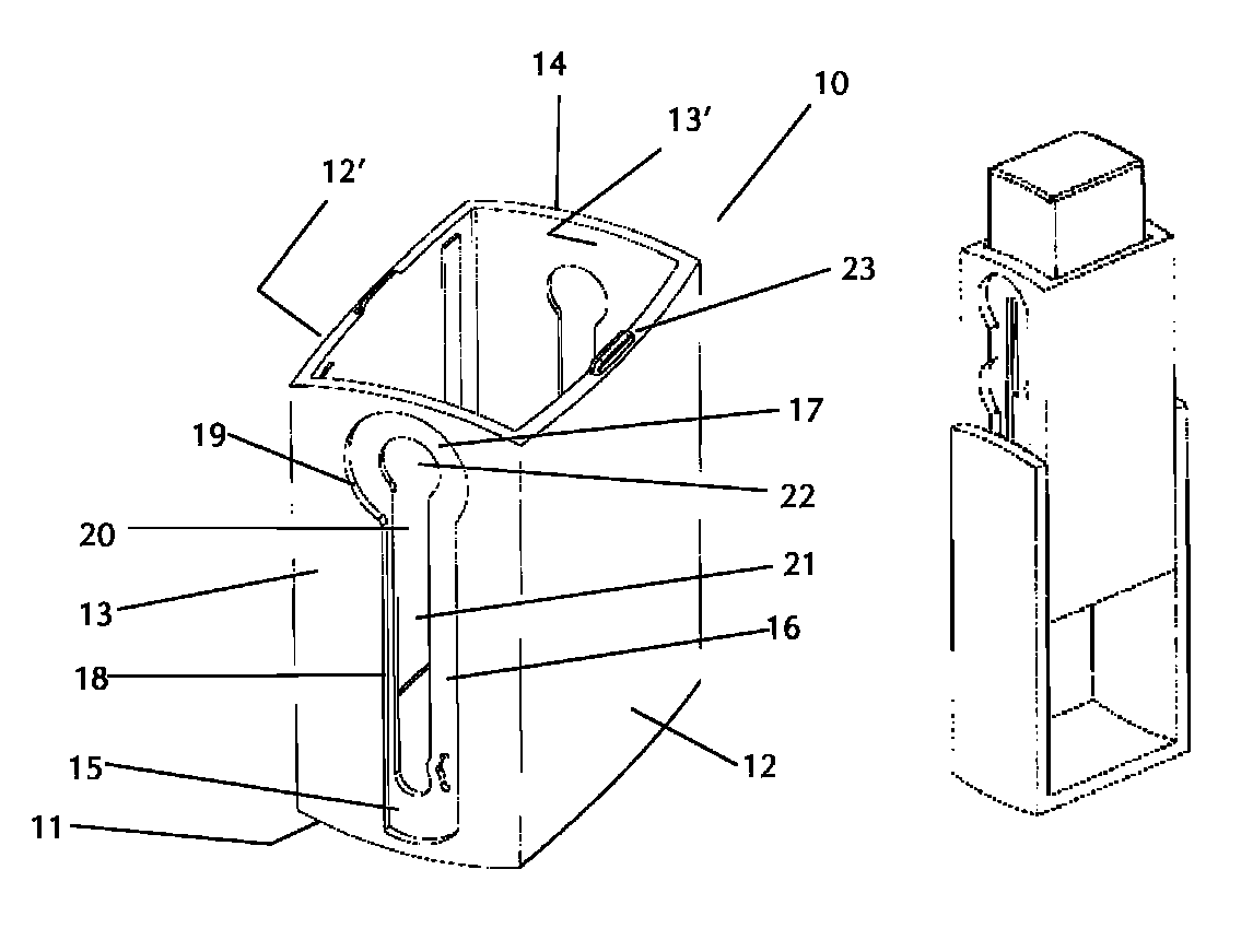
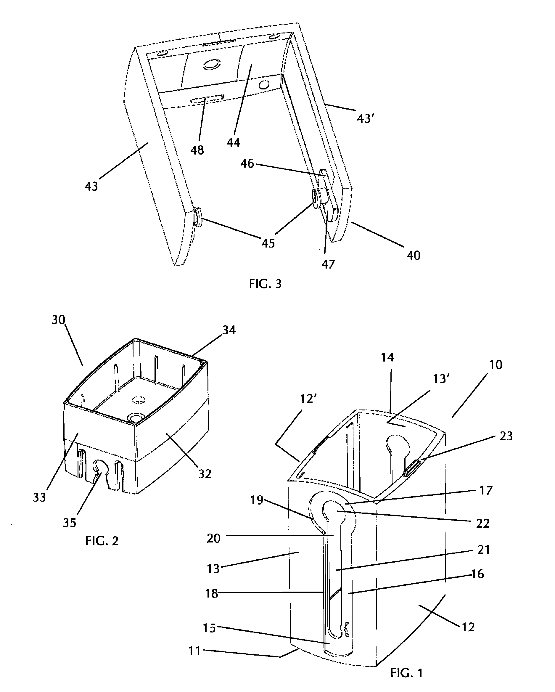
[0037]In one embodiment (see FIG. 1), the base (10) comprises at least one recessed section (15) and at least one groove within the recess. Preferably, the base comprises two recesses, one on each lateral wall (13, 13′) of the base. Each recess is in two sections. One section is a relatively long, straight recess (16) that runs vertically, along a lateral wall of the base. Approaching the top of the base, the straight recess opens into a circular recess (17). The circular recess has a diameter that is larger then the width of the straight recess. The entire recess is defined by a recess wall that bounds the recess. The straight recess is bounded on both sides by straight, parallel sections (18) of the recess wall. The circular recess is bounded by a circular section (19) of the recess wall. Within each recess is a groove (20). The groove is substantially straight and may or may not have a circular portion at the top end of the groove. In the embodiment shown in the FIG. 1, the groov...

example 2

[0047]The following example is somewhat simpler than the previous and shown in FIGS. 8a-8e. To reveal the detail underneath, FIG. 8 shows the working of a compact, with a portion of the cap (140) cut away. Again, the groove (200) may be thought of as comprising two parts, a straight groove (210) and an offset circular groove (220). In this embodiment, the circular groove (or a functional equivalent) is required. The straight groove runs vertically, along a lateral wall of the base (110) and opens into the offset circular groove. Unlike the previous example, there is no recess surrounding the groove. The circular groove is offset from the center line of the straight groove, such that one edge of the straight groove is substantially tangent to the perimeter of the circular groove. Furthermore, the offset of the circular groove on one side of the base is opposite to the offset on the other side of the base. The reason for this will be made clear, below.

[0048]The pivots (145) project fr...

example 3

[0050]The following example is very similar to the example 2 and shown in FIGS. 9a-9e. To reveal the detail underneath, FIG. 9 shows the working of a compact, with a portion of the cap (140) cut away. Again, the groove (200) may be thought of as comprising two parts, a straight groove (210) and an offset circular groove (320). In this embodiment, the circular groove (or a functional equivalent) is required. The straight groove runs vertically, along a lateral wall of the base (110) and opens into the offset circular groove. Again, there is no recess surrounding the groove. The circular groove is offset from the center line of the straight groove, but not as much as in example 2. Thus, the edge of the straight groove is not tangent to the perimeter of the circular groove. As before, the offset of the circular groove on one side of the base is opposite to the offset on the other side of the base.

[0051]The pivots (245) project from each interior surface of the lateral sections of the c...


PUM


Abstract

The present invention is a convenient-to-use cosmetic compact of increased stability, comprising a base, a cosmetic article carrier disposed within the base and a cap. With respect to the base, the cap is sometimes capable of translational movement and sometimes capable of rotational movement, but the cap can only perform one type of motion at a time. The type of movement that the cap may execute, depends on the relative orientation of the cap and base. There is one exception to this rule. There is exactly one orientation of the cap with respect to the base from which the user may execute either translation or rotation, but not both simultaneously.Translation of the cap with respect to the base causes translation of the cosmetic article carrier, either toward the bottom or toward the top of the base. In contrast, rotation of the cap with respect to the base does not affect the position of the cosmetic article carrier. Preferably, the cap is capable of rotating at least 180°.A selective rotation mechanism decouples translational motion of the cap from rotational motion of the cap. Thus, compound movement of the cap, with respect to the base, is not possible. Inadvertent movement of the carrier is eliminated, because when the device is in an orientation for use, translational movement of the carrier is prohibited. This feature creates greater stability during use. The device may be operated with one fluid motion by the user.

Description

FIELD OF THE INVENTION[0001]The present invention relates to the packaging of various personal care articles, such as cosmetic or dermatologic products and ancillary items, such as brushes or other applicators. Specifically, the present invention concerns improved compact devices of unitary construction whose components can be oriented by a user to expose the cosmetic article for use.BACKGROUND[0002]There are many containers whose cap and base can be reoriented by a user to expose an enclosed article for use. Of concern here, is a type of container having a cap that is capable of translation and rotation with respect to a base and wherein an article carrier translates within the base to expose or hide the article.[0003]In all of the following patents (U.S. Pat. Nos. 234,280; 238,959; 947,198; 1,693,151; 1,734,117; D148,294; 2,556,500; 3,033,258; D197,368; 4,915,527; D360,057; 5,391,011; 6,200,051), the cap can rotate and translate simultaneously. This features are disadvantageous. T...

Claims


Application Information

Patent Timeline
Patent Type & Authority Patents(United States)
IPC IPC(8): B65D43/20
CPCA45D33/006A45D33/28A45D40/023A45D40/221A45D2040/225A45D33/00A45D40/00
Inventor CORBELLINI, FRANCISBOUIX, HERVE
Owner ELC MANAGEMENT LLC
Learn More