
Controller for AC generator

a control system and ac generator technology, applied in the direction of electric generator control, windings, cooling/ventilation arrangement, etc., can solve the problems of affecting the operation of the generator, and the rotor of the claw-pole type, etc., to achieve the effect of efficient cooling

Inactive Publication Date: 2010-08-03
MAGNETIC APPL
View PDF27 Cites 13 Cited by
  • Summary
  • Abstract
  • Description
  • Claims
  • Application Information

AI Technical Summary

Benefits of technology

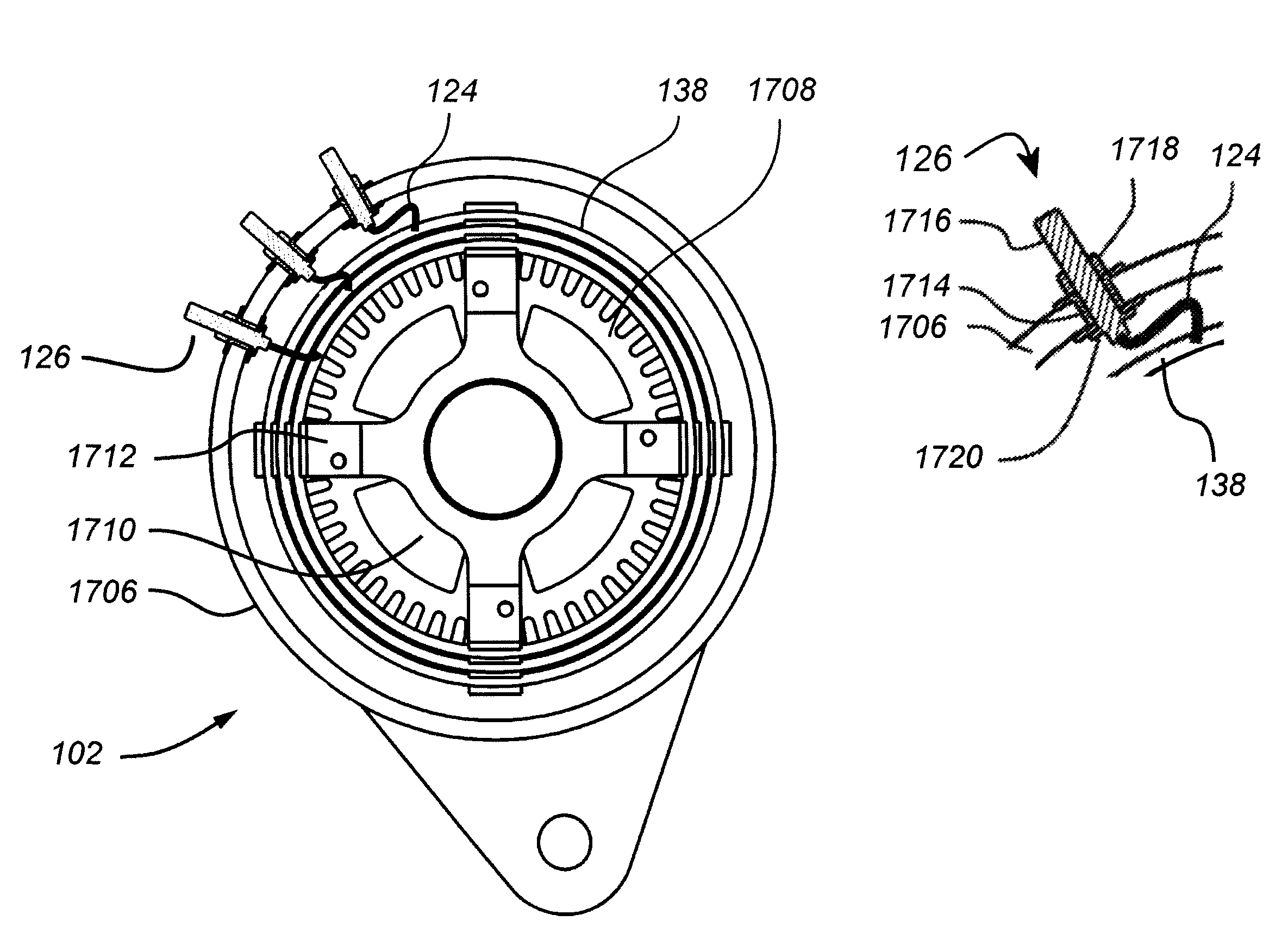
"The present invention provides a control system for a generator that can handle changes in output with relatively uniform phase ripple. The system uses a trigger signal based on the time integral of the voltage in the AC signal half cycle or only in response to zero crossings. An automatic gain system compensates for component value differences between channels. The control system can also compensate for losses in long cable runs and optimize battery charging voltage based on battery temperature. The system includes mechanisms to reduce battery plate sulfation and monitor and optimize various system parameters. The stator winding is wound with a predetermined number of pole phase coils connected in parallel, and a conducting phase ring is installed for each output phase to facilitate cooling and grouping and transmission of output phases to the control system. The conducting phase rings are held in place by a non-conducting support structure and are disposed to provide efficient cooling."

Problems solved by technology

Accordingly, space constraints in vehicles tend to make such alternators difficult to use in high output, e.g. 5 KW, applications, such as for powering air conditioning, refrigeration, or communications apparatus.
In addition, the claw-pole type rotors, carrying windings, are relatively heavy (often comprising as much as three quarters of the total weight of the alternator) and create substantial inertia.
Such inertia, in effect, presents a load on the engine each time the engine is accelerated.
This tends to decrease the efficiency of the engine, causing additional fuel consumption.
In addition, such inertia can be problematical in applications such as electrical or hybrid vehicles.
The use of such electrical control and drive systems tends to increase the demand on the electrical power system of the vehicle.
Typically only a limited amount of space is provided within the engine compartment of the vehicle to accommodate the alternator.
Unless a replacement alternator fits within that available space, installation is, if possible, significantly complicated, typically requiring removal of major components such as radiators, bumpers, etc. and installation of extra brackets, belts and hardware.
Such voltage levels are difficult and, indeed, dangerous to handle.
In addition, such extreme variations in the voltage and current may require more expensive components; components rated for the high voltages and currents produced at high engine RPM (e.g. highway speeds) are considerably more expensive, than components rated for more moderate voltages.
However, particularly in compact high power, high speed ratio applications such as motor vehicles, the switching transitions between windings have deleterious effects, especially at the high end of the RPM range.
These solutions tend to involve mechanical components that are large, require maintenance and are subject to wear.
Flux diversion, however, typically requires additional mechanical components and can be slow to react.
The range of output signals that can be generated from a given AC signal level (and thus range of input AC signals) is thus limited, as compared to a full controlled system.
The variations in ripple contents in the output of the bridge can produce unacceptable output ripple harmonics and require extensive filtering.
For example, the outputs of many alternators are not a uniform sine wave.
Such distortions and non-uniformities in the alternator output can occur for any of a number of reasons, such as, for example, variations in the placement of the winding turns relative to each other and, in the case of permanent magnet alternators, relative to the magnets.
In addition, the output of the generator often includes spurious components (e.g. spikes) that can be mistaken for zero crossings by the detector circuitry.
For example, the operation of alternator systems can be significantly affected, and sometimes disabled, by the temperature of the system components.
In alternator systems used to charge batteries, battery temperature has a direct impact on the optimal battery charging voltage and battery sulfation is a major contributor to shortened battery life.
Several problems can exist with this winding method.
For example: because of the low number of turns (in some instances only a single turn) per pole phase coil, it is difficult or impossible to make a small change in design output voltage by changing the number of turns of the phase pole coil; the large cross sectional area of the conductors make the stator difficult to wind; and a short circuit between coils will typically burn out the entire stator and may stall the alternator, resulting in possible damage to the drive system or overloading the vehicle engine.

Method used


Image

  • Controller for AC generator
  • Controller for AC generator
  • Controller for AC generator

Examples


Embodiment Construction

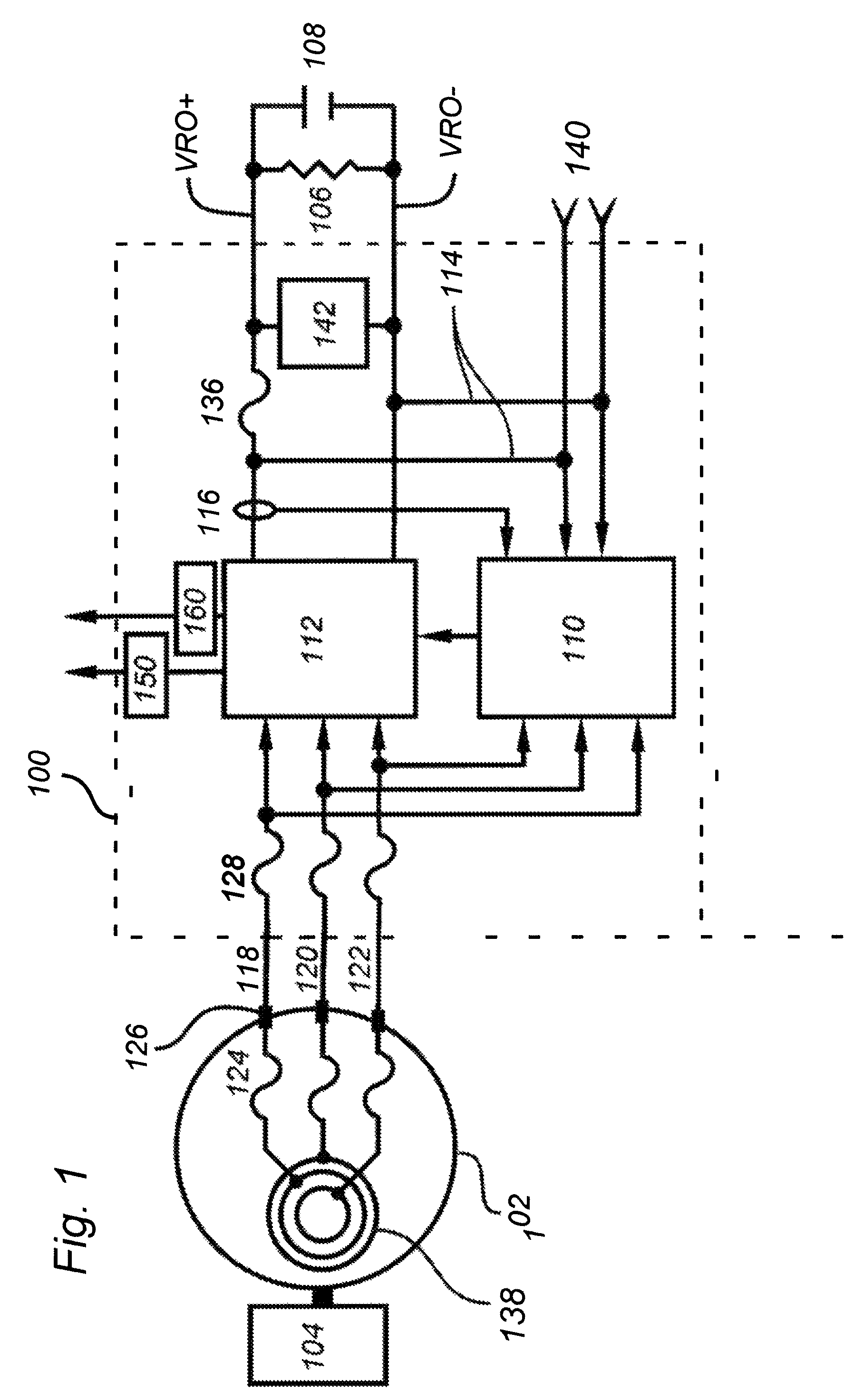
[0073]Referring now to FIG. 1, a system 100 for converting between mechanical and electrical energy in accordance with various aspects of the present invention comprises a controller 110 and a switching bridge 112. System 100 suitably cooperates with a source of AC power, such as an alternator 102 and a source of mechanical energy (e.g. drive) 104, e.g. an engine or turbine, a load 106, such as a motor and, if desired, in energy storage device 108, such as a battery, capacitor, or flywheel. If desired, an inverter (sometimes categorized as comprising part of load 106) can also be provided to generate an AC signal at a constant predetermined frequency and amplitude (e.g. 60 Hz, 120V).

[0074]In general, alternator 102 generates AC power in response to mechanical input from energy source 104. Alternator 102 preferably provides multi-phase (e.g. three-phase, six-phase, etc.) AC output signals, e.g. phase A (118), phase B (120), and phase C (122). Those output signals are typically unregu...


PUM


Abstract

A control system that can accommodate the wide variations in the output of a generator, such as a permanent magnet alternator, while providing an output with relatively uniform phase ripple. The control system includes a zero crossing detector and variable ramp generator for generating control signals to a switching rectifier to generate a regulated DC signal.

Description

CROSS REFERENCE TO RELATED APPLICATIONS[0001]This application is a continuation of and claims full benefit of and priority to U.S. patent application Ser. No. 11 / 347,777, filed Feb. 2, 2006 now U.S. Pat. No. 7,327,123, the disclosure of which is hereby fully incorporated by reference for all purposes.TECHNICAL FIELD OF THE INVENTION[0002]The present invention relates to voltage and current control systems for machines for converting between mechanical and electrical energy, such as brushless AC generators, and in particular to a control system for a compact permanent magnet high power alternator, such as a compact permanent magnet high power alternator suitable for automotive use.BACKGROUND OF THE INVENTION[0003]An alternator typically comprises a rotor mounted on a rotating shaft and disposed concentrically relative to a stationary stator. The rotor is typically disposed within the stator. However, the stator may be alternatively positioned concentrically within the rotor. An exter...

Claims


Application Information

Patent Timeline
Patent Type & Authority Patents(United States)
IPC IPC(8): H02K3/04
CPCH02P9/48H02P2101/45H02K3/12H02K3/24H02K3/50
Inventor SCOTT, HAROLD C.WILLIAMS, DAVE E.LAFONTAINE, CHARLES Y.
Owner MAGNETIC APPL
Learn More