
Catalytic converter with improved start-up behaviour

Inactive Publication Date: 2010-08-03
UMICORE AG & CO KG
View PDF8 Cites 3 Cited by
  • Summary
  • Abstract
  • Description
  • Claims
  • Application Information

AI Technical Summary

Benefits of technology

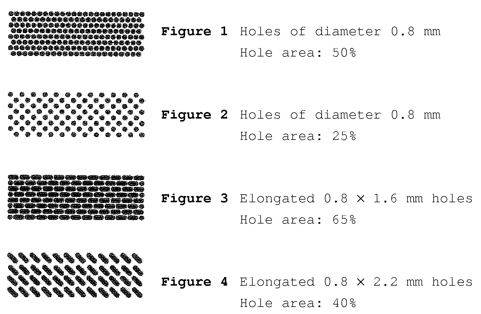
[0011]The present invention shall avoid the disadvantages known from the prior art of perforated sheet layers. It is an object of the invention to compensate for the loss of support surface through the hole surface of the sheet layers by means of suitable measures.
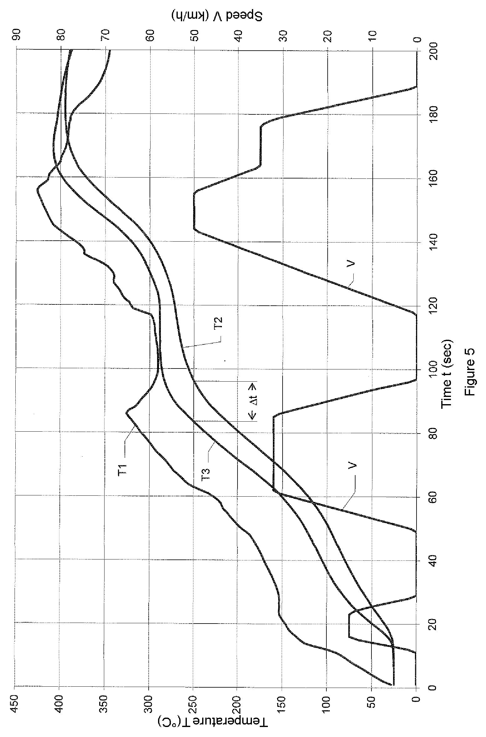
[0015]The advantage according to the invention is that the perforations of the sheet layers do not lead to a reduction in the amount of catalyst material. As a consequence, the inventive catalyst, as a result of the reduced heat capacity of the support, reaches its lightoff temperature very rapidly and then displays the full activity of the unreduced amount of catalyst coating. Furthermore, the inventive catalyst, owing to the higher loading concentration with catalyst material, has an improved aging stability over conventional perforated catalysts.
[0016]Of course, it would also be possible to apply the same coating concentration in accordance with the prior art without closing the holes on the honeycomb. However, the coating thickness would then inevitably be significantly greater and would thus lead to a higher flow resistance of the catalyst.
[0017]To prepare the inventive catalyst, the properties of the coating suspension have to be adjusted to the hole dimensions in order to ensure complete filling of substantially all holes with catalyst material. Low viscosity coating suspensions can close only small holes; viscous coating suspensions, in contrast, cover even relatively large holes. The person skilled in the art can easily determine the optimal conditions by a few preliminary experiments.
[0021]In this way, as in the case of unperforated honeycombs, according to the coating thickness desired, it is possible to achieve coating concentrations between 50 and 400 grams per liter of volume of the honeycomb. If the intention were to apply the same coating concentration without closing the holes, the coating thickness on the sheets would have to be increased correspondingly.
[0029]The corrugated surface of the expanded metal has an advantageous effect on the catalytic action of the finished catalyst, since it swirls the exhaust gas within the flow channels of the catalyst and hence improves the contact with the catalyst coating. However, it increases the exhaust gas back pressure. When this is not desired, the expanded metals can be flattened by rolling before the catalyst body is formed.

Problems solved by technology

Moreover, such a catalyst, owing to the small amount of catalyst material, has a low aging resistance.
Furthermore, the perforation in the sheet layers increases the back pressure of the catalyst, since turbulence forms at the holes.
If the intention were to apply the same mass of catalyst material as in the case of an unperforated support with the same geometry to such a catalyst support, the layer thickness of the catalyst layer and hence likewise the back pressure of the catalyst would inevitably increase.

Method used


Image

  • Catalytic converter with improved start-up behaviour
  • Catalytic converter with improved start-up behaviour
  • Catalytic converter with improved start-up behaviour

Examples


example 1

Comparative Catalyst (Catalyst A)

[0045]A cylindrical metal honeycomb composed of unperforated metal foils of 0.05 mm thickness, a diameter of 90 mm, a length of 74.5 mm and a cell density of 200 cm−2 was coated with a conventional three-way catalyst comprising platinum, palladium and rhodium with a noble metal concentration of 1.55 g / l of honeycomb volume.

example 2

Inventive Catalyst (Catalyst B)

[0046]For comparison of the catalytic properties, a further supported metal catalyst with the same dimensions, foil thicknesses and the same cell density as the comparative catalyst was produced. Instead of unperforated metal foils, however, an expanded metal with a stretching of 30% and a mesh length of 0.6, a mesh width of 0.5 and a strand width of 0.18 mm was used. The metal support was coated with the same three-way catalyst in the same concentration as the comparative catalyst.

[0047]FIG. 6a) shows a photograph of the structure of the expanded metal used prior to catalytic coating. FIG. 6b) shows a corresponding photograph after catalytic coating. It can be seen clearly that the mesh orifices of the expanded metal have been filled completely with catalyst material. The catalyst material adhered in an outstanding manner on the expanded metal and showed no detachment even in the case of blowing with compressed air and knocking.

Back Pressure Measureme...


PUM

PropertyMeasurementUnit
Lengthaaaaaaaaaa
Lengthaaaaaaaaaa
Fractionaaaaaaaaaa

Abstract

In automotive exhaust gas catalysts with a metallic honeycomb composed of corrugated and smooth sheet layers, it is known that the heat capacity and thermal conductivity of the honeycomb can be reduced by perforations in the sheet layers. As a result, the honeycomb heats up more rapidly and the catalytic coating applied on the honeycomb reaches its operating temperature more rapidly. A disadvantage here is the reduction in the support surface area by the perforations in the sheet layers. According to the invention, suitable adjustment of the properties of the coating suspension used for the catalytic coating and of the dimensions of the holes relative to one another allows the holes to be filled permanently with catalyst material. The resulting catalyst has, at the same coating concentration as a catalyst with unperforated sheet layers, a significantly reduced heat capacity and thermal conductivity.

Description

[0001]The present invention addresses metallic honeycombs as supports for a coating of catalyst material for the exhaust gas cleaning of internal combustion engines.BACKGROUND OF THE INVENTION[0002]What is desired from the honeycombs is firstly a large geometric surface area to accommodate the coating and secondly a low heat capacity in order that the honeycomb warms up rapidly to the operating temperature of the catalyst. In addition, a sufficient mechanical stability is required from the honeycombs in order to withstand the mechanical stresses through the pulsating gas flow and the vibrations of engine and vehicle. Moreover, the material of the honeycomb has to be resistant to the corrosive exhaust gas atmosphere at high temperatures.[0003]The catalytic coating of a finished catalyst consists of finely divided thermally stable metal oxides on whose surface are deposited catalytically active platinum group metals. Suitable metal oxides are, for example, aluminum oxide, titanium oxi...

Claims


Application Information

Patent Timeline
IPC IPC(8): B01J21/04
CPCB01D46/2418B01D53/9454B01J35/04B01J37/0225F01N3/281B01D46/2451B01D46/2466B01D2046/2481B01D2046/2492Y02T10/22Y02A50/20Y02T10/12B01D46/249B01D46/2486B01J35/56F01N3/28F01N3/24B01D46/2484B01D46/247B01D46/2496
Inventor QUELL, JUERGEN
Owner UMICORE AG & CO KG
Learn More