
Method of reading a capacitive sensor and related integrated circuit

a capacitive sensor and integrated circuit technology, applied in the field of capacitive sensors, can solve the problems of affecting the precision of the sensing (reading) system of these sensors, preventing the realization of relatively low-cost systems for reading such capacitive pressure sensors with good precision, etc., and achieve the effect of low cos

Active Publication Date: 2010-07-13
STMICROELECTRONICS SRL
View PDF7 Cites 28 Cited by
  • Summary
  • Abstract
  • Description
  • Claims
  • Application Information

AI Technical Summary

Benefits of technology

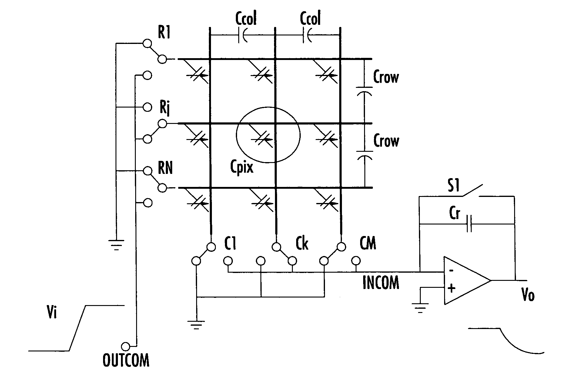
The present invention provides a method and system for reading a capacitive sensor that overcomes the problems of previous methods. The system can be made at a low cost and can be used with sensors of different numbers of rows and columns. The method involves preliminary resetting of the output voltage of a charge amplifier, connecting to a reference voltage all the deselected row and column plates of the array, and applying a step voltage on the selected capacitor and reading the output voltage at steady-state. The method also contemplates scanning all the capacitors of the array to obtain as many values of capacitances and periodically updating the distribution map of pressure on the sensor area in time. The integrated reading system for a capacitive sensor includes an input interface circuit, a biasing and reading circuit, an analog-to-digital converter, a microprocessor unit, and an output interface circuit.

Problems solved by technology

Several problems have so far prevented realization of relatively low cost systems for reading such capacitive pressure sensors with good precision and with a great flexibility of use such to make them usable in particularly demanding applications.
The precision of the sensing (reading) system of these sensors is negatively affected by the fact that the reading of the capacitance of a capacitor of the array is disturbed by the presence of the other capacitors and by parasitic capacitances between adjacent rows and columns.

Method used


Image

  • Method of reading a capacitive sensor and related integrated circuit
  • Method of reading a capacitive sensor and related integrated circuit
  • Method of reading a capacitive sensor and related integrated circuit

Examples


Embodiment Construction

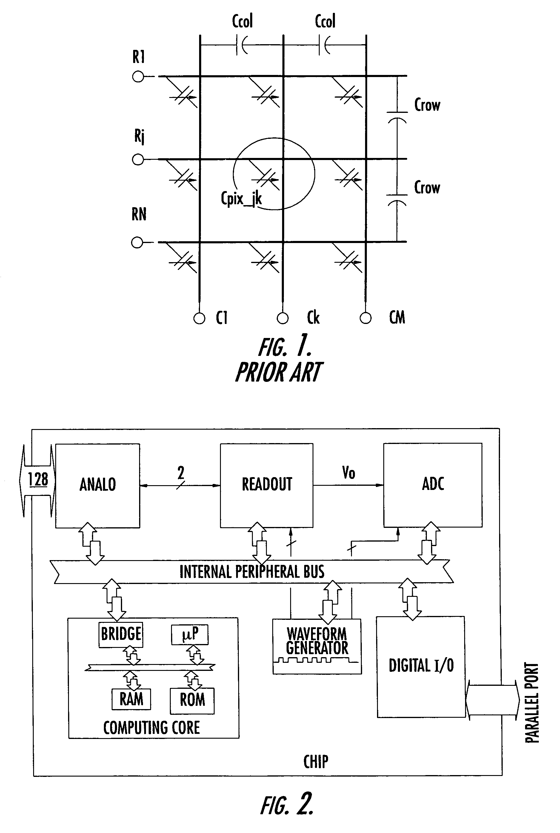
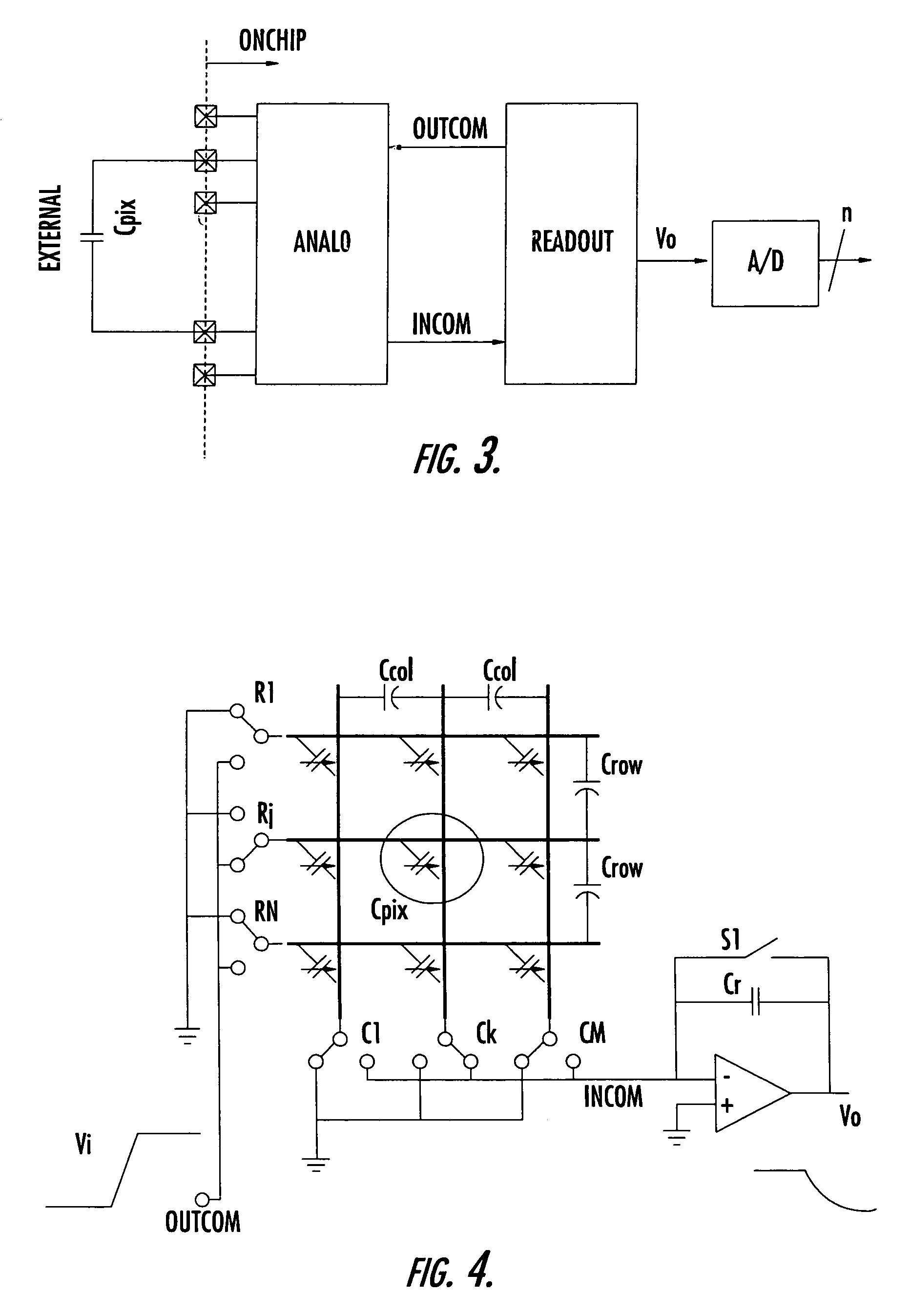
[0019]A preferred embodiment of the system of the invention, that may be readily integrated, is depicted in FIG. 2, in the form of block diagram. It includes an input interface block ANAIO, a biasing and reading block READOUT, an analog to digital conversion block ADC, a control block COMPUTING CORE and an output digital interface DIGITALI / O. In practice, the input interface ANAIO couples the selected capacitor CPIX to be read to the biasing and reading circuit READOUT producing a voltage signal Vo representative of the capacitance of the read capacitor and grounds the plates of substantially all deselected capacitors of the sensor array. An analog-to-digital converter ADC converts the analog voltage V0 in a corresponding multibit datum of bit vector.

[0020]The processing and control function are executed via an internal bus INTERNAL PERIPHERAL BUS by a control block COMPUTING CORE that comprises a microprocessor unit μP, ROM, RAM and BRIDGE. The control may also optionally and prefe...


PUM


Abstract

The method is for reading a capacitive sensor and may be implemented by a circuit for biasing and reading capacitances that includes circuits for selecting a column line and a row line, and a charge amplifier producing an output voltage representing the capacitance of the selected capacitor intercepted by the selected column and row lines. The method includes preliminarily resetting the output voltage of the charge amplifier, connecting all the deselected row and column plates of the array to a reference voltage and connecting a feedback capacitor and the selected capacitor to an inverting input of the amplifier, applying a step voltage on the capacitor that is connected to the inverting input of the amplifier, and reading the output voltage at steady-state.

Description

FIELD OF THE INVENTION[0001]The present invention relates to the field of capacitive sensors, and more particularly to methods and integrated systems for reading a plurality of capacitors of a capacitive sensor including an array of capacitors.BACKGROUND OF THE INVENTION[0002]Capacitive sensors are largely used as contact or pressure sensors. According to a particular embodiment, they may comprise an array of capacitors ordered in rows and columns connected through row and column lines (or plates), as schematically depicted in FIG. 1. These sensors produce a distribution map of the pressure even on a relatively large surface. The capacitance of each single capacitor of these sensors depends on the degree of deformation undergone by the dielectric layer of the capacitor, induced by a compressive force exerted thereon. By reading the values of the capacitances of all the capacitors of the array, an “array” of values (“frame”) describing the spatial distribution of the pressure field o...

Claims


Application Information

Patent Timeline
Patent Type & Authority Patents(United States)
IPC IPC(8): H04N5/335H04N3/14H04N25/00G01D5/24
CPCG01D5/24
Inventor SERGIO, MAXIMILIANMANARESI, NICOLTARTAGNI, MARCOCANEGALLO, ROBERTO
Owner STMICROELECTRONICS SRL
Learn More