
Light fixture alignment tool

Inactive Publication Date: 2010-07-06
COSIMANO HARRY
View PDF11 Cites 33 Cited by
  • Summary
  • Abstract
  • Description
  • Claims
  • Application Information

AI Technical Summary

Benefits of technology

[0021]It is therefore a primary object of the present invention to provide a luminaire alignment aid apparatus that is simple in design and may be used to quickly, easily and precisely align spotlights, floodlights, and the like at or toward a desired horizontal and vertical point or location.
[0022]It is a further object of the present invention to provide a high intensity confined beam light which can be entered into a directional light source in place of a normal bulb of such directional light source and aid when electrically activated to align the directional light source.
[0025]It is a still further object of the present invention to provide a method of expeditiously aiming a directional light having an adjustable mounting by removing any light bulb in the directional light, temporarily replacing such light bulb in the directional light with a laser light fitting adapted for electrical or non electrical connection with the socket, activating the laser light, and aiming the light fixture while the laser light is activated so that the laser light is pointing in the desired direction, after which the laser light may be replaced by the normal light bulb which will be correctly oriented for best illumination.
[0028]It is a still further object of the present invention to provide a method of quickly and easily aligning a light source so that the light is emitted in a preselected direction.
[0033]It is a still further object of the invention to provide a high intensity confined beam light temporarily mountable in a light socket to provide a narrow beam of high intensity light toward the area to be illuminated with a switch operating the narrow beam high intensity light being operable by rotation of a portion of the outer casing for the light and incorporating a safety interlock preventing the high intensity light from being activated by rotation of such light casing in the direction usually used for unscrewing of a bulb from an electric socket.
[0035]An apparatus for quickly and accurately aiming and aligning commercial or household directional lights or luminaires such as floodlights, track lighting, spotlights and the like, which tool utilizes a conventional battery operated laser light source that is secured in an opening in one end of an electrically non-conductive housing. Situated on the opposite end of said housing is a socket engaging member for connecting the apparatus in a bulb socket of a light fixture to be aligned. The socket engaging member in a preferred embodiment is comprised of a plurality of spaced apart flexible prongs dimensioned to fit in a bulb socket, and wherein when pressed downwardly or inwardly into the socket the prongs are moved inwardly toward one another. The operation or activation of the laser pointer is controlled by rotating it either directly or by means of a tight fitting in the socket housing, whereby a switch on the side of the laser light is moved in and out of a detent in the side surface of the socket opening, causing the switch to turn the device off and on. Once secured in the socket, the longitudinal axis of the tool and laser pointer correspond with the longitudinal axis of the socket, so that by adjusting the horizontal and vertical position of the light base, the light can be precisely aimed at a desired point or area. The alignment tool is then pulled out of or otherwise removed from the socket and the standard bulb inserted, with the device already being properly directionally aligned to illuminate such desired point or area. In an alternative embodiment, the laser pointer housing is rotated into and out of the electric socket by means of a more or less conventional threaded fitting. In a preferred embodiment of the invention, a cap or outer shroud may be mounted on the outer end of the laser pointer to protect the laser light and serve as a means to turn the light on and off. In a still further preferred embodiment, this outer cap or shroud is arranged to only turn with respect to the casing in a clockwise direction.

Problems solved by technology

This can be inconvenient and time-consuming, however, particularly if several or even a large number of lights must be properly aimed, or if the position of such lights must be adjusted periodically.
Often, it is visually difficult to determine if a light is correctly aligned, due to the brightness of the light and angle at which it is being viewed, and the correct position may never be achieved.
On the other hand, if such lights are not properly aligned their practical or decorative effectiveness and desirability may be significantly diminished.
Shibla does not disclose the use of a laser light to properly align the direction of another light source, however.
While laser light may be electrically connected to the socket base for the main light of the garage door opener system, such laser light is not physically mounted in the light socket.
In addition, while U.S. Pat. No. 4,160,285 issued to Shibla teaches the use of a laser light to point to a specific location, such reference also does not teach the temporary mounting of a laser light aiming device in a light socket to aid in aiming a floodlight or spotlight type luminaire.
Thus, while the prior art devices discussed above are useful for their own particular indicated purposes and uses, none exhibits the particular features of the present inventor's luminaire alignment aid apparatus that make such apparatus significantly easier and less time-consuming to use.

Method used


Image

  • Light fixture alignment tool
  • Light fixture alignment tool
  • Light fixture alignment tool

Examples


Embodiment Construction

[0051]The following detailed description is of the best mode or modes of the invention presently contemplated. Such description is not intended to be understood in a limiting sense, but to be an example of the invention presented solely for illustration thereof, and by reference to which in connection with the following description and the accompanying drawings one skilled in the art may be advised of the advantages and construction of the invention.

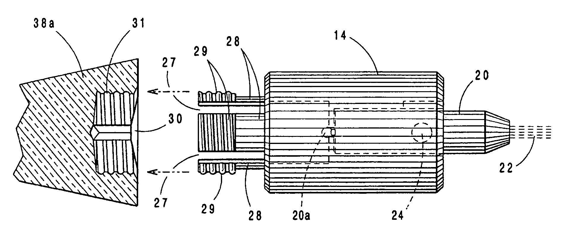
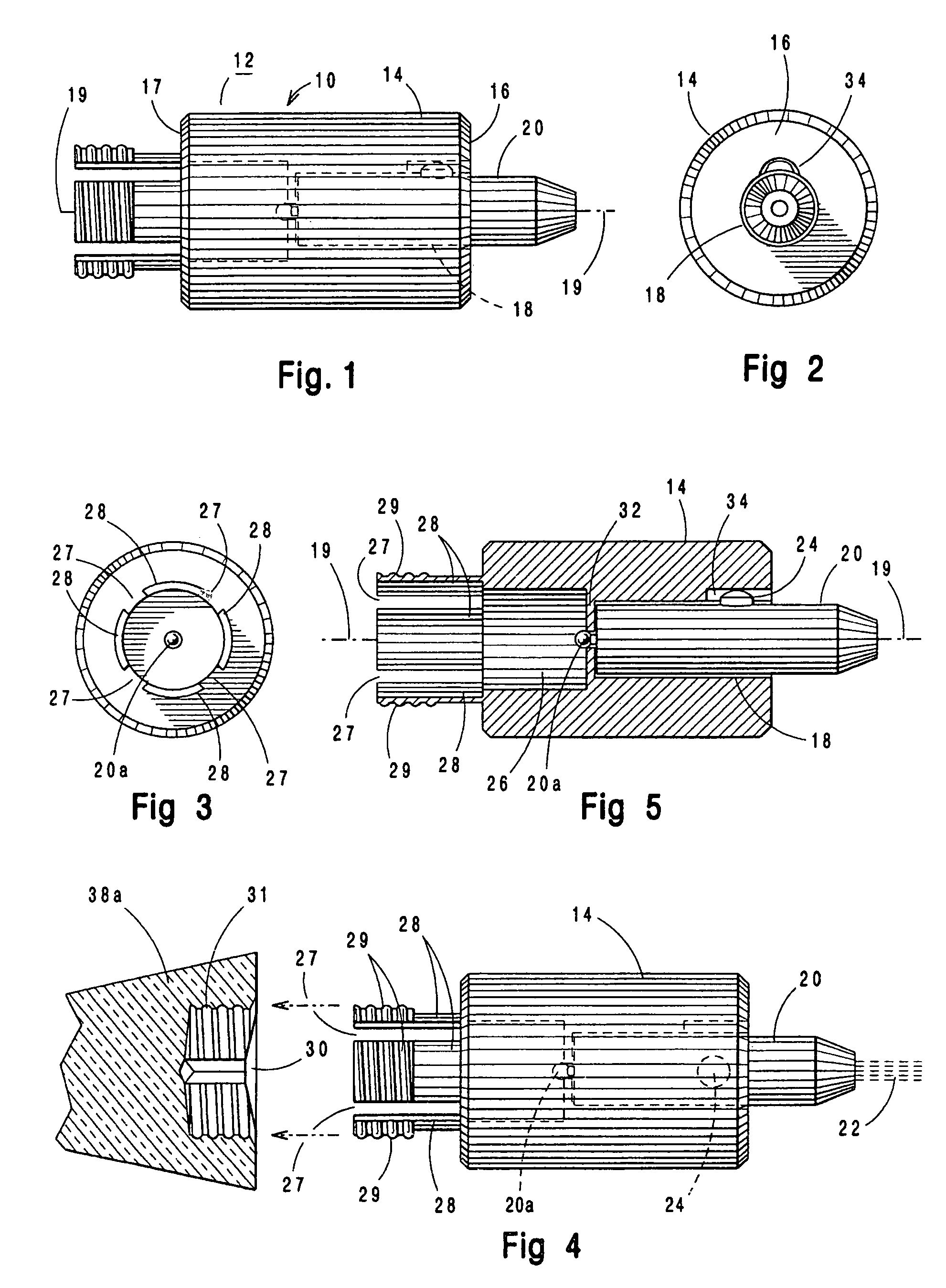
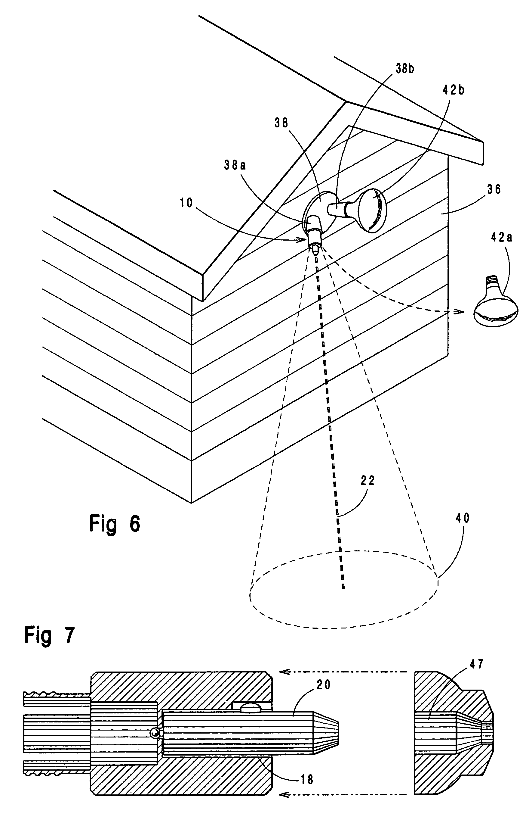
[0052]As indicated and reviewed above, there have been a number of laser light aligning devices devised and used in the past. However, none have been completely suitable for aligning directional lights around the home or business in a simple and convenient manner. The present inventor has unexpectedly realized that such a simple and effective laser light alignment apparatus can be provided by the user of a laser apparatus with a constricted beam of light for mounting temporarily directly in the light socket of a directed light to be alig...


PUM


Abstract

An apparatus and method for aiming and aligning a light wherein a laser light source is mounted in an electrically non-conductive housing having a socket engaging section enabling the apparatus to be mounted in the socket of a light fixture to be aligned, wherein by adjusting the light fixture so that the beam emitted from said laser light source is directed at the desired aiming position for the light, the proper horizontal and vertical position for the light fixture can be quickly and accurately determined.

Description

BACKGROUND OF THE INVENTION[0001]1. Field of the Invention[0002]The present invention relates to devices for properly aligning a luminarie such as a spotlight, floodlight, track lighting, and the like, and more particularly to a laser light alignment tool that directs a concentrated light beam at the desired lighting location to enable alignment of a luminarie to be determined.[0003]2. Description of Related Art[0004]It is of course well known to mount luminaires such as floodlights and spotlights to the walls of a building, light standards, posts, ceiling, wall mounts, or the like, in both internal or indoor and external, or outdoor areas. Floodlights produce a broader light beam and are used to saturate a relatively large area with light, while spotlights direct a more narrow beam of light at a specific object or site, with reflectors in the light fixture being used to collimate the light beam into substantially parallel rays. Such interior and exterior lighting is routinely provi...

Claims


Application Information

Patent Timeline
IPC IPC(8): G01C15/00G01D21/00
CPCG01C15/002Y10S33/21
Inventor COSIMANO, HARRY
Owner COSIMANO HARRY
Learn More