
Responding a partial lead failure in an implantable cardioverter defibrillator

a cardioverter and partial lead technology, applied in electrotherapy, therapy, etc., can solve the problems of inability to provide therapy and inability to provide alternative lead configuration, and achieve the effect of reducing the voltage of the shocking puls

Active Publication Date: 2010-06-29
PACESETTER INC
View PDF17 Cites 40 Cited by
  • Summary
  • Abstract
  • Description
  • Claims
  • Application Information

AI Technical Summary

Benefits of technology

[0007]An implanted cardioverter defibrillator (ICD) delivers an electrical therapy signal to the heart of a patient. When ventricular fibrillation or another condition of the heart requiring high voltage therapy is sensed, the therapy signal (i.e., an electrical shocking pulse) is delivered to the heart. When a partial short-circuit or other low impedance condition occurs, an over-current protection circuit will stop deliver

Problems solved by technology

There are times, however, when an effective, alternate lead configuration is not available.
Furthermore, failing to deliver therapy can be problematic if the therapy signal was required to sustain a patient's life.

Method used


Image

  • Responding a partial lead failure in an implantable cardioverter defibrillator
  • Responding a partial lead failure in an implantable cardioverter defibrillator
  • Responding a partial lead failure in an implantable cardioverter defibrillator

Examples


Embodiment Construction

[0015]The following detailed description refers to the accompanying drawings that illustrate exemplary embodiments. Other embodiments are possible, and modifications may be made to the embodiments. Therefore, the following detailed description is not meant to limit. Rather, the scope of the invention is limited only by the appended claims.

[0016]It will be apparent to one of skill in the art that the one or more embodiments, as described below, may be implemented in many different embodiments of hardware, software, and / or firmware. Any actual software and / or hardware described herein is not limiting of the one or more embodiments. Thus, the operation and behavior of the one or more embodiments will be described with the understanding that modifications and variations of the embodiments are possible, given the level of detail presented herein.

[0017]Before describing the one or more embodiments in detail, it is helpful to describe an example environment. The present embodiments are use...


PUM


Abstract

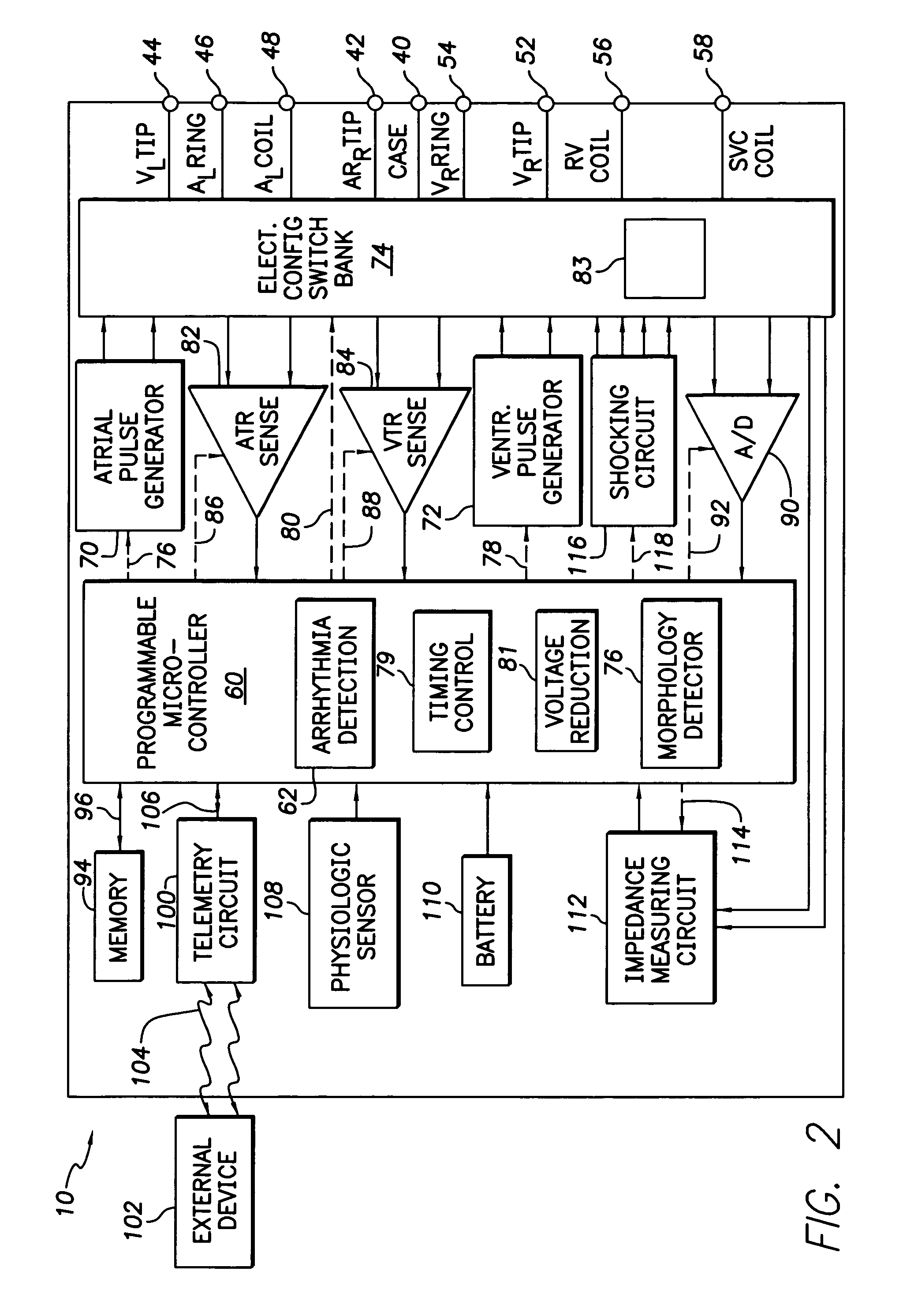
An implanted cardioverter defibrillator (ICD) delivers an electrical therapy signal to the heart of a patient. When ventricular fibrillation or another condition of the heart requiring high voltage therapy is sensed, the therapy signal is delivered to the heart. When a partial short-circuit or other low impedance condition occurs, an over-current protection circuit will stop delivery of a shocking pulse. The ICD will then reduce the voltage of the shocking pulse and try again to deliver electrical therapy. This process is repeated until a voltage level is found that is able to deliver the electrical therapy without causing an over-voltage condition. Alternate lead configurations may also be tried in an attempt to find a signal path that is not affected by the low impedance or short-circuit condition.

Description

BACKGROUND[0001]1. Field of the Invention[0002]The present invention relates generally to implantable cardioverter defibrillators (ICDs) and, more particularly, to preserving ICD functionality in the event of lead failure.[0003]2. Background Art[0004]An implantable cardiac device is a medical device that is implanted in a patient to monitor electrical activity of a heart and to deliver appropriate electrical and / or drug therapy, as required. Implantable cardiac devices include, for example, pacemakers, cardioverters, defibrillators, and the like. The term “implantable cardioverter defibrillator” or simply “ICD” is used hereinafter to refer to any implantable cardiac device.[0005]The ICD includes one or more electrodes that interact with the heart. Before delivering a signal to the heart from the ICD via the electrodes, it is desirable to first check the state of a signal path to determine, for example, if a low impedance or short-circuit like condition exists. A short-circuit like c...

Claims


Application Information

Patent Timeline
IPC IPC(8): A61N1/00
CPCA61N1/3931A61N1/3621A61N2001/083
Inventor KROLL, MARK W.MOUCHAWAR, GABRIEL A.MOULDER, J. CHRISTOPHERWALKER, ANDRE
Owner PACESETTER INC
Learn More