Electro-optical device and electronic apparatus

a technology of electronic equipment and optical devices, applied in the field of heat dissipation devices, can solve the problems of increasing the possibility of adverse effects, and increasing the power consumption

Inactive Publication Date: 2010-06-29
138 EAST LCD ADVANCEMENTS LTD
View PDF12 Cites 2 Cited by
  • Summary
  • Abstract
  • Description
  • Claims
  • Application Information

AI Technical Summary

Benefits of technology

[0009]Since the main body section of the heat dissipater according to the first aspect of the invention has the hollow-sleeve shape described above, it is possible to install the heat dissipater in a relatively space-efficient manner while ensuring that the main body section, which functions to dissipate heat, has a relatively large surface area. Thus, the heat dissipater according to the first aspect of the invention makes it possible to produce a high heat-dissipation effect with a space-saving structure. In addition to the above, the heat dissipater according to the first aspect of the invention offers another advantage in that the flexible substrate and the integrated circuit are protected against any kind of mechanical stress that could be applied from the outside of the main body section because the main body section covers the flexible substrate, which is inserted inside the main body section, and the integrated circuit, which are mounted on the flexible substrate.
[0010]As explained above, the heat dissipater according to the first aspect of the invention makes it possible to produce a high heat-dissipation effect with a space-saving structure, and in addition thereto, to protect the flexible substrate and the integrated circuit against any kind of mechanical stress that could be applied from the outside of the main body section thereof.
[0013]Since the main body section of the heat dissipater according to the first aspect of the invention has the open portion described above, it is relatively easy to insert the flexible substrate into the main body section thereof in, for example, the production process of the heat dissipater according to the first aspect of the invention. It should be noted that the width of the open portion could be arbitrarily determined depending on the size of the flexible substrate that is inserted through and inserted inside the main body section, although other factor(s) may be used in addition to or in place of the size of the flexible substrate. Therefore, it is possible to reduce the load of assembly / disassembly work that is necessitated due to the attachment / fixation of the heat dissipater according to the first aspect of the invention.
[0015]With such a configuration, since the open portion is formed, in the main body section, at a region that includes at least a part of a region opposite to the adhering section, the integrated circuit, which is adhered to the main body section via the adhering section, is provided on the “rear” surface of the flexible substrate, where the term “rear” is defined as one surface that is remoter from the open portion than the other opposite surface thereof. Therefore, it is possible to protect the integrated circuit against any kind of mechanical stress that could be applied from the outside of the main body section with a further protection effect.
[0017]Since the electro-optical device according to the second aspect of the invention is provided with the heat dissipater according to the first aspect of the invention described above, it is possible to effectively dissipate heat that is generated / produced at the integrated circuit that is mounted on the flexible substrate. Therefore, it is possible to provide an electro-optical device that is substantially free from any kind of a malfunction and / or an operation failure / error that is attributable to undesirable heat generated / produced during the operation thereof. Thus, the electro-optical device according to the second aspect of the invention features considerably enhanced operation reliability.
[0020]Since the heat dissipater is fixed to the electro-optical panel as described above, when the electro-optical panel is installed as, for example, a light valve inside an electronic apparatus such as a projector, though not limited thereto, it is possible to determine (i.e., fix) the position of the electro-optical panel in the electronic apparatus, which is easily achieved by attaching the heat dissipater to the electronic apparatus. This means that the electro-optical device according to the second aspect of the invention makes it possible to determine the position of the electro-optical panel in the electronic apparatus without any necessity to attach the electro-optical panel directly to the electronic apparatus. Therefore, as a non-limiting example of advantages thereof, it is possible to avoid the emission of light from being obstructed due to any positional shift or positional deviation of the electro-optical panel, which serves as a light valve, inside the electronic apparatus.

Problems solved by technology

These days, as the processing power of the driving integrated circuit increases, so does the power consumption thereof.
Due to the increased power consumption, the amount of heat generated during the operation of the driving integrated circuit is also on the rise.
For this reason, there is an adverse and increasing possibility that the thermal runaway and / or the thermal destruction of an electro-optical device may occur because of undesirable heat that is produced by the driving integrated circuit.

Method used


Image

  • Electro-optical device and electronic apparatus
  • Electro-optical device and electronic apparatus
  • Electro-optical device and electronic apparatus

Examples


Embodiment Construction

[0031]With reference to the accompanying drawings, exemplary embodiments of the present invention are described below.

Heat Dissipation Member

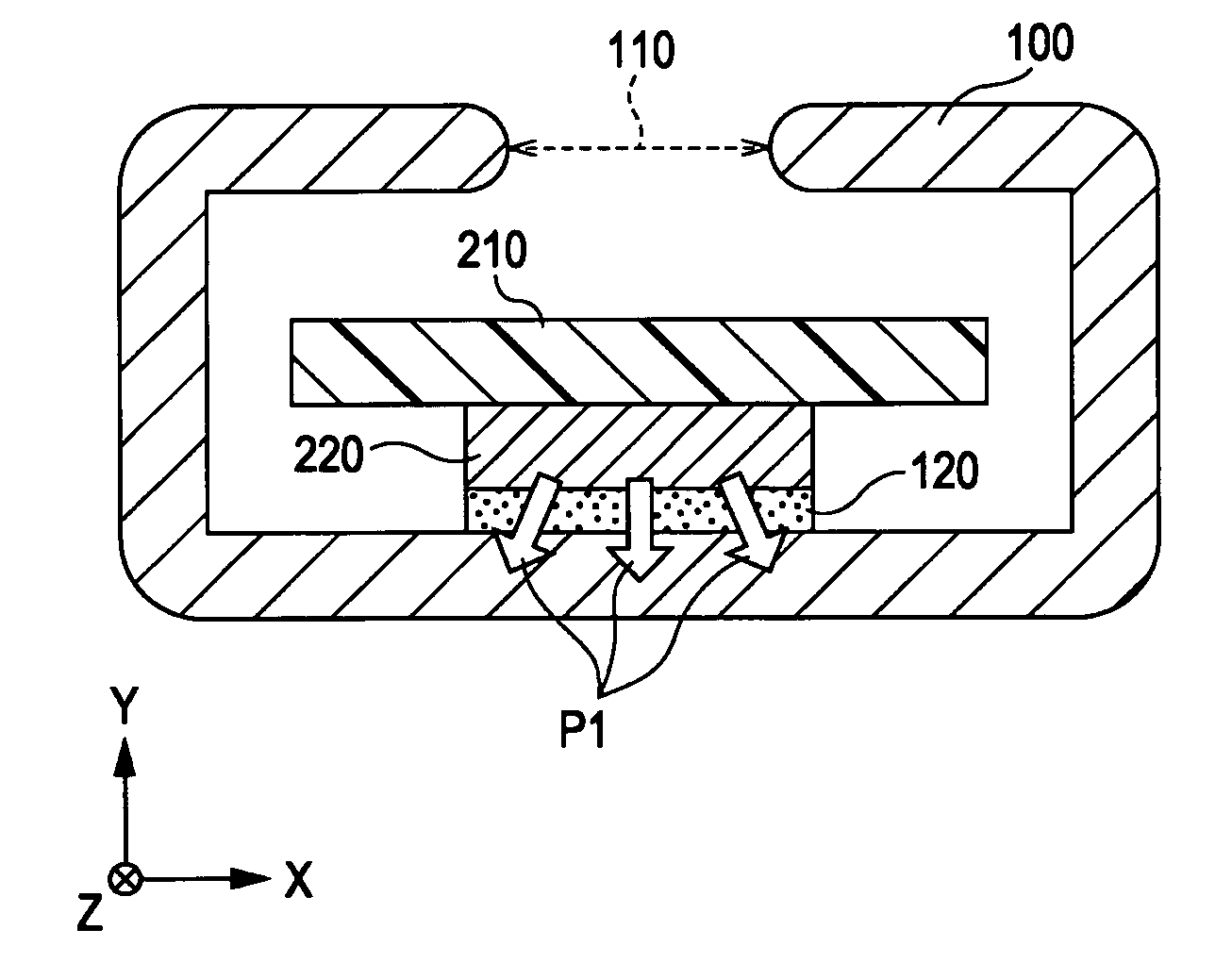
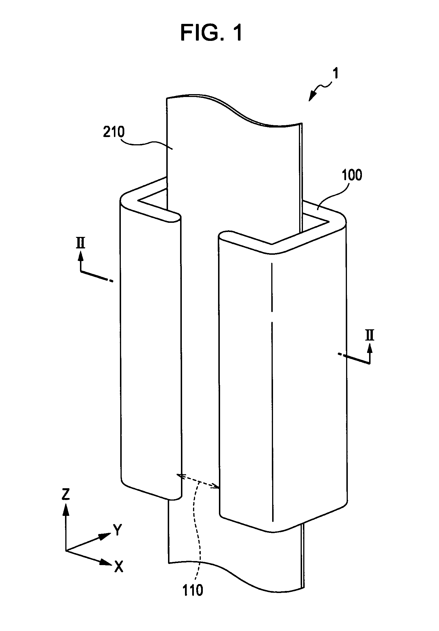
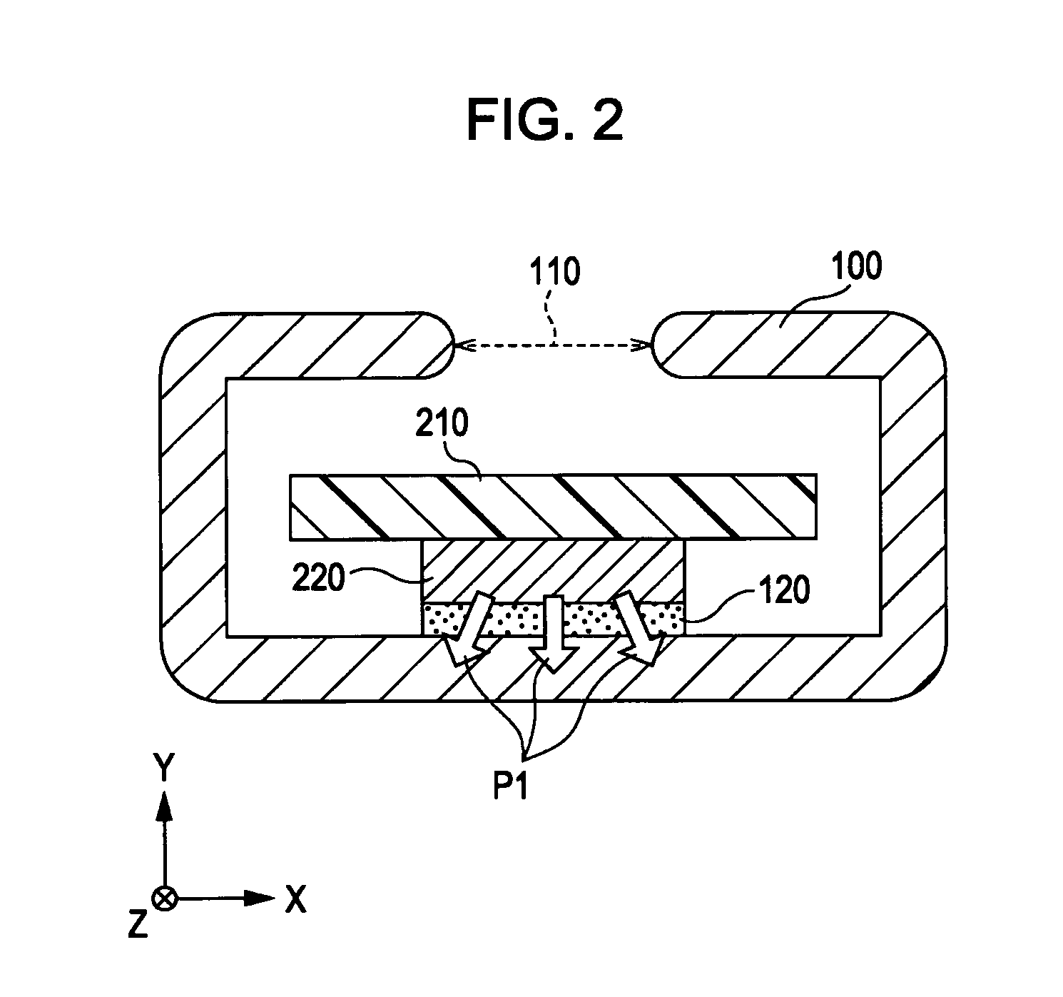
[0032]First of all, with reference to FIGS. 1 and 2, a heat dissipation member according to the present embodiment of the invention is explained below. FIG. 1 is a perspective view that schematically illustrates an example of the configuration of a heat dissipation member through which a flexible printed circuit board is inserted. FIG. 2 is a sectional view that schematically illustrates an example of the configuration of the heat dissipation member taken along the X-Y plane of FIG. 1.

[0033]As illustrated in FIGS. 1 and 2, a heat dissipation member (e.g., heat radiation member, heat release member, though not limited thereto) 1 according to the present embodiment of the invention is provided with, though not necessarily limited thereto, a main body portion 100 and an adhesive portion 120. The main body portion 100 of the heat dissipation member...


PUM


Abstract

The invention provides a heat dissipater such as a heat dissipation member that dissipates heat of an integrated circuit that is formed on a flexible substrate such as a flexible printed circuit board. The heat dissipater according to an aspect of the invention includes; a main body section that is formed in the shape of a hollow sleeve in such a manner that the flexible substrate can be inserted through and inserted inside the main body section; and an adhering section that is formed on an inner surface of the main body section in such a manner that the main body section and the integrated circuit are adhered to each other via the adhering section.

Description

BACKGROUND[0001]1. Technical Field[0002]The present invention relates to a heat dissipater such as a heat dissipation member or the like that radiates heat undesirably generated at an integrated circuit that is mounted on a flexible substrate such as a flexible printed circuit board or the like. The flexible printed circuit board to which the heat dissipater according to an aspect of the invention is applied is used, for example, in a liquid crystal device without any intention of limitation thereto. In addition, the invention relates to an electro-optical device that is provided with such a heat dissipater, and further to an electronic apparatus that is provided with such an electro-optical device. A non-limiting example of the electronic apparatus according to an aspect of the invention is a liquid crystal projector.[0003]2. Related Art[0004]In the technical field to which the electro-optical device according to an aspect of the invention pertains, there is an electro-optical devi...

Claims


Application Information

Patent Timeline
Patent Type & Authority Patents(United States)
IPC IPC(8): H05K1/18
CPCG02F1/13452G02F1/133385
Inventor ITO, MASAAKI
Owner 138 EAST LCD ADVANCEMENTS LTD
Why Eureka
Try Eureka