
Biometrics system and biometrics method

a biometric system and biometric technology, applied in the field of biometric system and biometric method, can solve the problems of user confusion, unsatisfactory verification results, and inability to obtain verification results, so as to improve the speed of authentication and convenience for users

Inactive Publication Date: 2010-06-22
FUJITSU LTD +1
View PDF14 Cites 24 Cited by
  • Summary
  • Abstract
  • Description
  • Claims
  • Application Information

AI Technical Summary

Benefits of technology

[0016]Hence one object of this invention is to provide a biometrics system and biometrics method to effectively guide a body part at the time of authentication so as to coincide with the body part image capture circumstances at the time of registration, in order to improve verification efficiency.
[0018]Still a further object of this invention is, at the time of a verification error, to guide the body part to the circumstances of body part image capture at the time of registration without causing confusion on the part of the user, in order to effect convenience of use of biometric authentication for the user.
[0032]In this invention, the captured image for authentication is registered in advance at the time of biometric registration, and at the time of biometric authentication the captured image is displayed and provided to the user for use in image capture; hence convenience to the user is increased, with advantages for operation by a user not familiar with the authentication system and for improving the speed of authentication.

Problems solved by technology

However, when such guidance is performed, if the circumstances of body part detection at the time of registration differ from the circumstances of body part image capture at the time of authentication despite this guidance into the image capture range, satisfactory verification results cannot be obtained.
Thus even when the position and orientation of the hand or face are similar, often the verification results fail to match.
In the latter technology of the prior art, the shape of a hand is used together with an authentication algorithm, so that when there is authentication failure, the user does not directly understand the cause, and often it is not possible to determine how the body part should be guided with respect to the image capture device.
In particular, persons with little experience with the device, and elderly and other persons, will tend to experience inconvenience.
Consequently from the standpoint of the device manufacturer, because there are cases in which unanticipated events occur and verification errors may arise, it is expected that in such cases, if the user, if the individual in question, will lose confidence in such biometrics authentication.
Particularly when used in automated equipment (automated cash transaction machines, automated vending machines, in entrance doors to dwellings, and similar), because dedicated personnel are not on site, trouble is incurred in determining the cause of the problem, giving rise to a further loss of confidence in biometrics authentication.

Method used


Image

  • Biometrics system and biometrics method
  • Biometrics system and biometrics method
  • Biometrics system and biometrics method

Examples


first embodiment

of a Biometrics System

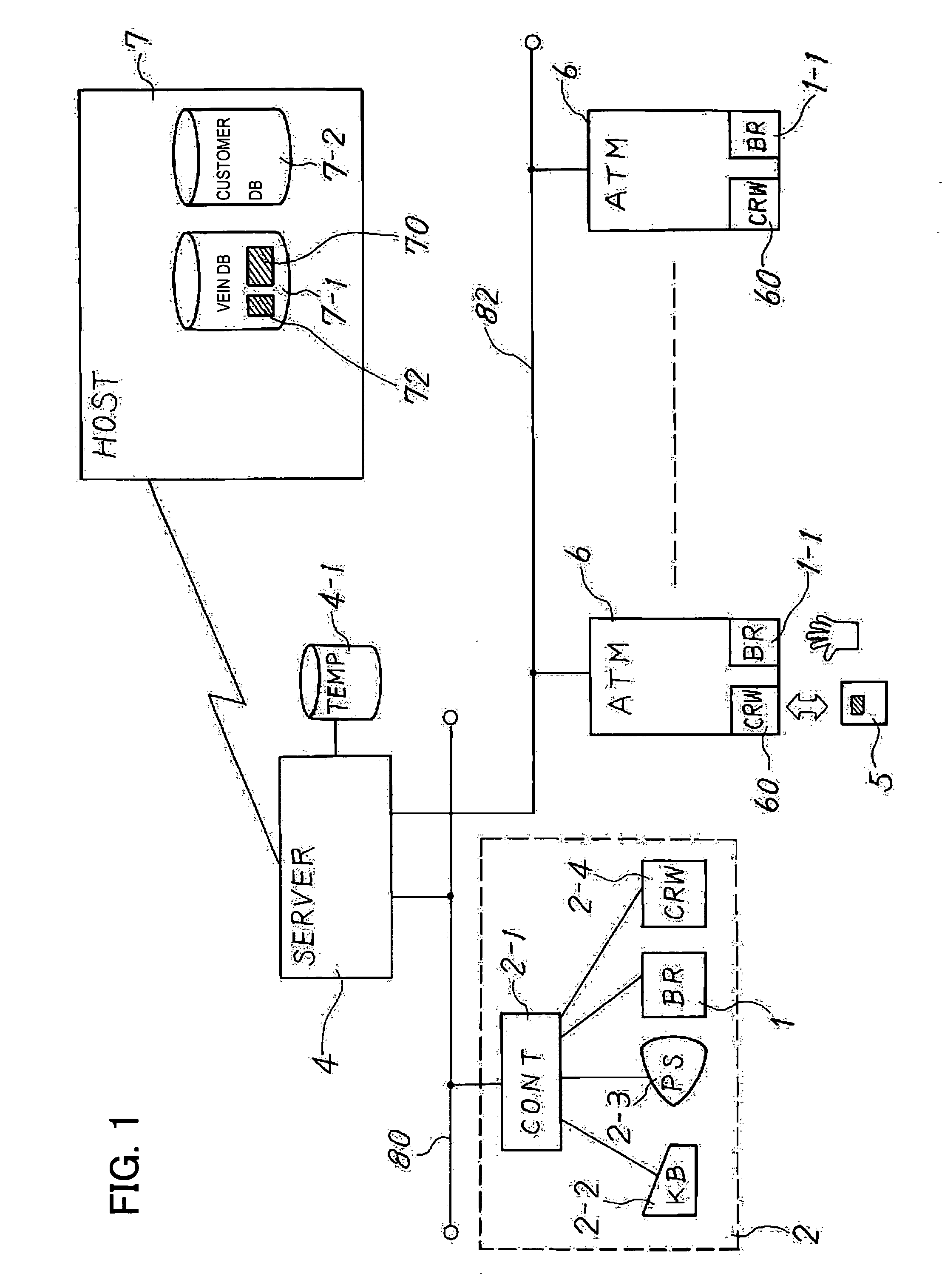
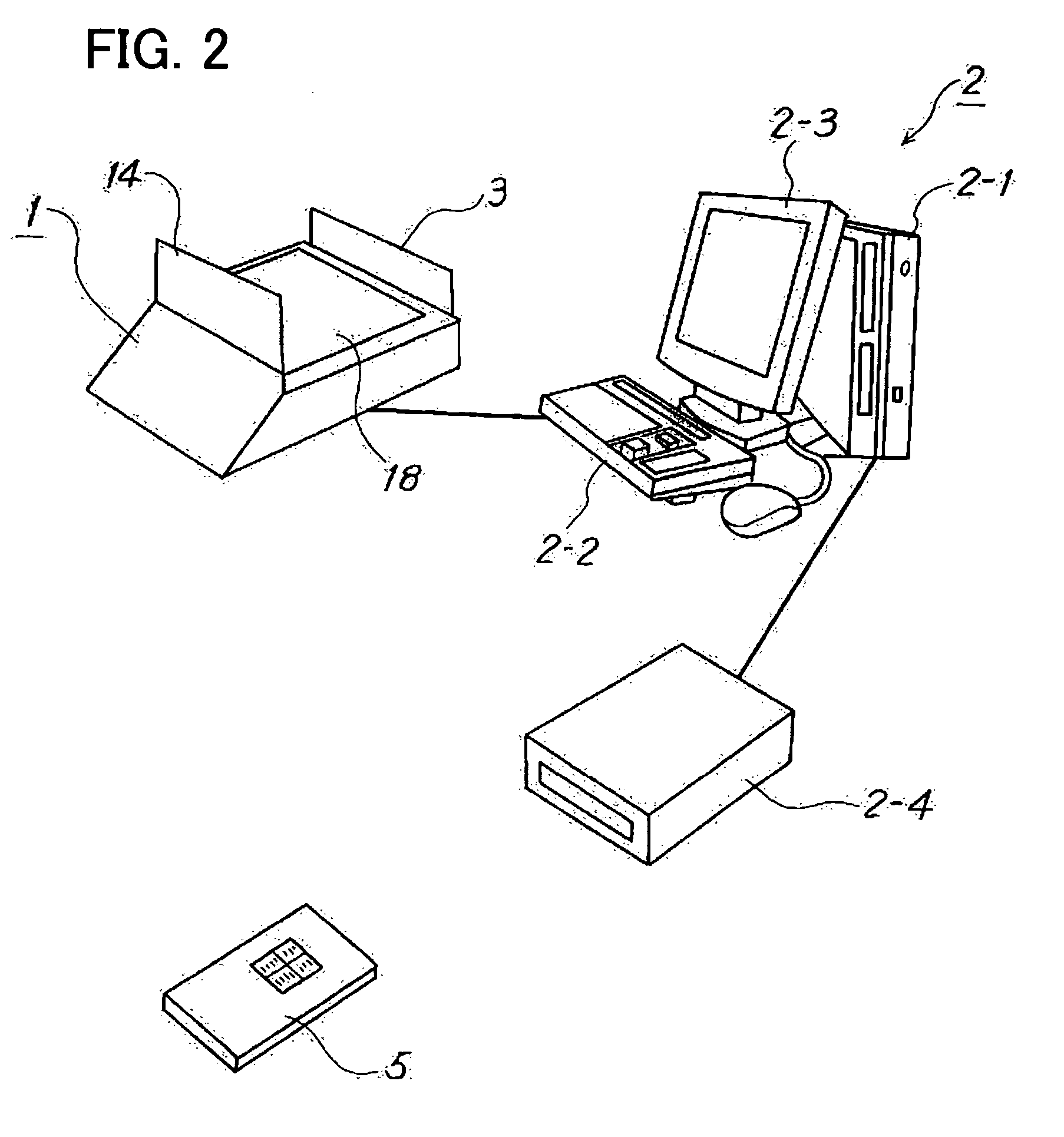
[0049]FIG. 1 shows the configuration of a first embodiment of a biometrics system of this invention, FIG. 2 shows the configuration of the service area device of FIG. 1, FIG. 3 is an external view of the automated transaction machine of FIG. 1, and FIG. 4 shows the configuration of the automated transaction machine of FIG. 3.

[0050]FIG. 1 shows a palm vein authentication system in a financial institution, as an example of a biometrics system. A branch terminal 2 is provided in a service area of the financial institution. As explained in FIG. 2, the branch terminal 2 is provided with a palm image capture device 1, a branch terminal computer (for example, a personal computer) 2-1 connected to the image capture device 1, a keyboard 2-2, a display 2-3, and an IC card reader / writer 2-4. The palm image capture device 1 may be configured integrally with the IC card reader / writer 2-4.

[0051]As indicated in FIG. 2, the palm image capture device 1 has a sensor unit 18, fro...

second embodiment

of a Biometrics System

[0119]FIG. 13 shows the configuration of the biometrics system of a second embodiment of the invention. In FIG. 13, similarly to FIG. 1, a palm vein authentication system in a financial institution is shown as an example of a biometrics authentication system. In FIG. 13, portions which are the same as in FIG. 1 are assigned the same symbols.

[0120]In FIG. 13, the branch terminal 2 explained in FIG. 2 is provided in a service area of the financial institution. As explained in FIG. 2, the branch terminal 2 is provided with a palm image capture device 1, and, connected thereto, a branch terminal computer (for example, a personal computer) 2-1, keyboard 2-2, display 2-3, and IC card reader / writer 2-4.

[0121]Similarly to FIG. 2, the palm image capture device 1 has a sensor unit 18, front guide 14 to support the wrist of the user, and a rear guide 13 to guide the fingers of the user. The user, having requested vein authentication, places his hand over this palm image c...

third embodiment

of a Biometrics System

[0131]FIG. 14 shows the configuration of a third embodiment of a biometrics authorization system of this invention. In FIG. 14, similarly to FIG. 1 and FIG. 13, a palm vein authentication system in a financial institution is shown, as an example of a biometrics system. In FIG. 14, portions which are the same as in FIG. 1 and FIG. 13 are assigned the same symbols.

[0132]In FIG. 14, a branch terminal 2 explained in FIG. 2 is provided in a service area of the financial institution. As explained in FIG. 2, the branch terminal 2 is provided with a palm image capture device 1, a branch terminal computer (for example, a personal computer) 2-1 connected to the image capture device 1, a keyboard 2-2, a display 2-3, and an IC card reader / writer 2-4.

[0133]Similarly to FIG. 2, the palm image capture device 1 has a sensor unit 18, front guide 14 to support the wrist of the user, and a rear guide 13 to guide the fingers of the user. The user, having requested vein authenticat...


PUM


Abstract

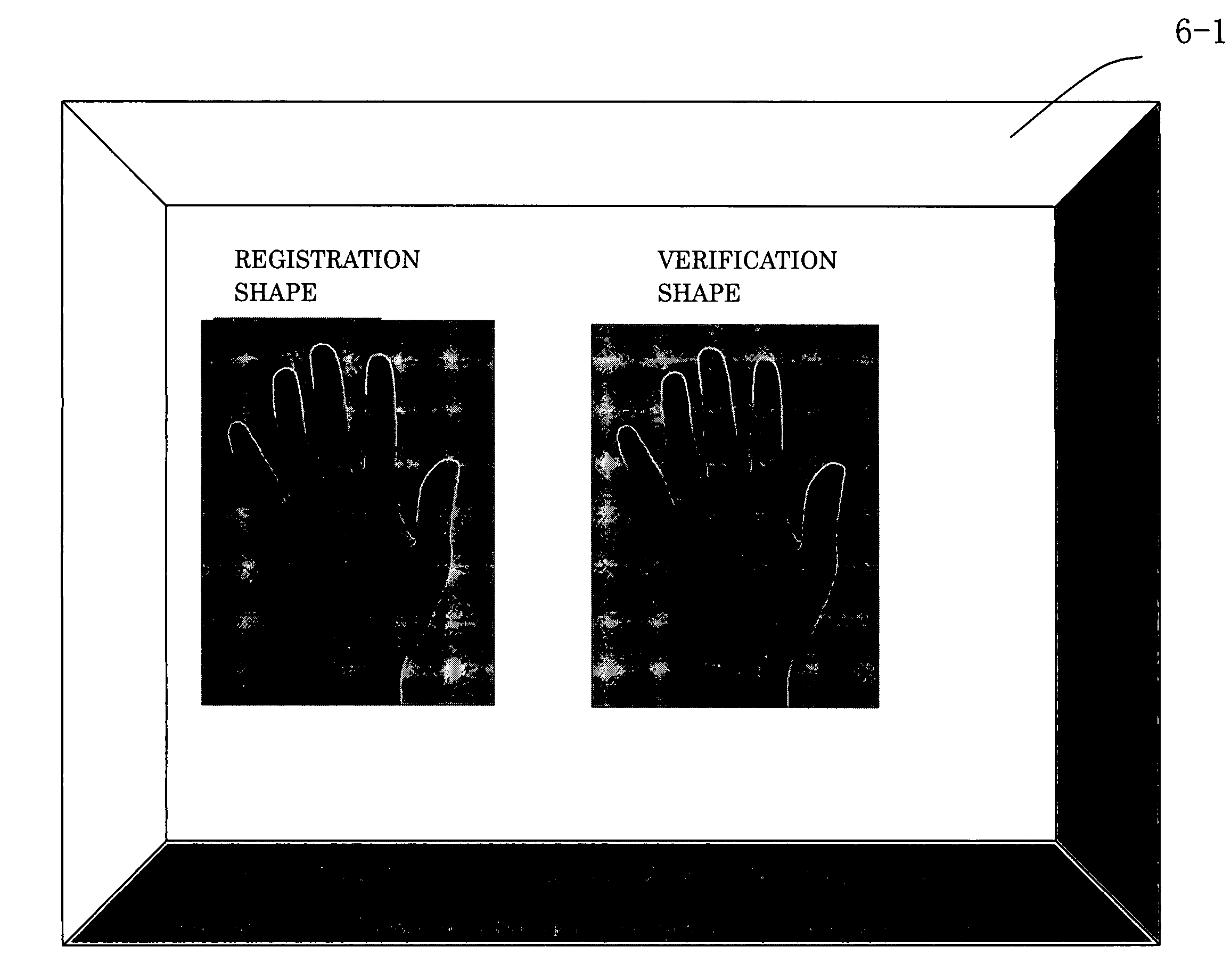
A biometrics authentication system that performs individual authentication in use of biometrics information facilitates authentication operation and reduces authentication errors. A storage unit stores therein the shape of the body part of the user, of which is captured at the time of registration of biometrics data, and a display unit displays the body part shape from the time of registration when authenticating the user for directly identifying the state of image capture of the body part at the time of registration and for guiding into a state of image capture of the body part similar to the state at the time of registration. The body part can be guided effectively such that the circumstances of body part image capture at the time of authentication and at the time of registration are in agreement, for improved verification efficiency.

Description

CROSS-REFERENCE TO RELATED APPLICATIONS[0001]This application is based upon and claims the benefit of priority from the prior Japanese Patent Application No. 2005-313092, filed on Oct. 27, 2005, the entire contents of which are incorporated herein by reference.BACKGROUND OF THE INVENTION[0002]1. Field of the Invention[0003]The present invention relates to a biometrics system and biometrics method utilizing characteristics of a portion of the human body to perform individual authentication, and in particular relates to a biometrics system and biometrics method which guide a body part into a state of registration when detecting biometrics information for use in verification against registered biometrics information.[0004]2. Description of the Related Art[0005]There exist numerous portions of the human body, such as fingerprints and toeprints, the retinas of the eyes, facial features, and blood vessels, which can be used to discriminate individuals. Advances in biometrics technology in...

Claims


Application Information

Patent Timeline
Patent Type & Authority Patents(United States)
IPC IPC(8): G06K9/00G06V10/24G06V40/10G06V40/14
CPCA61B5/117G06K9/00362G07C9/00087G06K9/32G06K9/00912G06K2009/00932G07C9/257G06V40/10G06V40/67G06V40/14G06V10/24G06F18/00
Inventor KAMATA, HIDEOTANAKA, HIROYUKI
Owner FUJITSU LTD
Learn More