Fire control system using a LIDAR (laser identification, detection and ranging) unit

a technology of lidar and fire control system, applied in the direction of weapons, reradiation, instruments, etc., can solve the problems of system performance becoming unpredictable, system is sensitive to non-uniformities, and system limitations based on this techniqu

Inactive Publication Date: 2010-06-22
STATE OF ISRAEL - SOREQ NUCLEAR RES CENT
View PDF7 Cites 36 Cited by
  • Summary
  • Abstract
  • Description
  • Claims
  • Application Information

AI Technical Summary

Benefits of technology

[0008]The present invention seeks to provide a Fire Control System (FCS) that is more accurate than any other prior art system. The invention is applicable over a wide range of turbulence strength changes and all wind fluctuations on paths longer than 500 m. The invention may provide automatic displacement of sight crosshairs in order to compensate for crosswind and drop of the bullet along the trajectory.

Problems solved by technology

The limitations of systems based on this technique become apparent when paths longer than 500 m are probed.
For cases of strong refractive turbulence strength Cn2, scintillations saturate, and the system performance becomes unpredictable.
Moreover, such a system is sensitive to nonuniformities along the propagation path (e.g., turbulence strength changes, wind fluctuations).
Nevertheless, no technique is ideal and the FT technique has its own limitations, mainly due to turbulence spectrum changes.

Method used


Image

  • Fire control system using a LIDAR (laser identification, detection and ranging) unit
  • Fire control system using a LIDAR (laser identification, detection and ranging) unit

Examples


Embodiment Construction

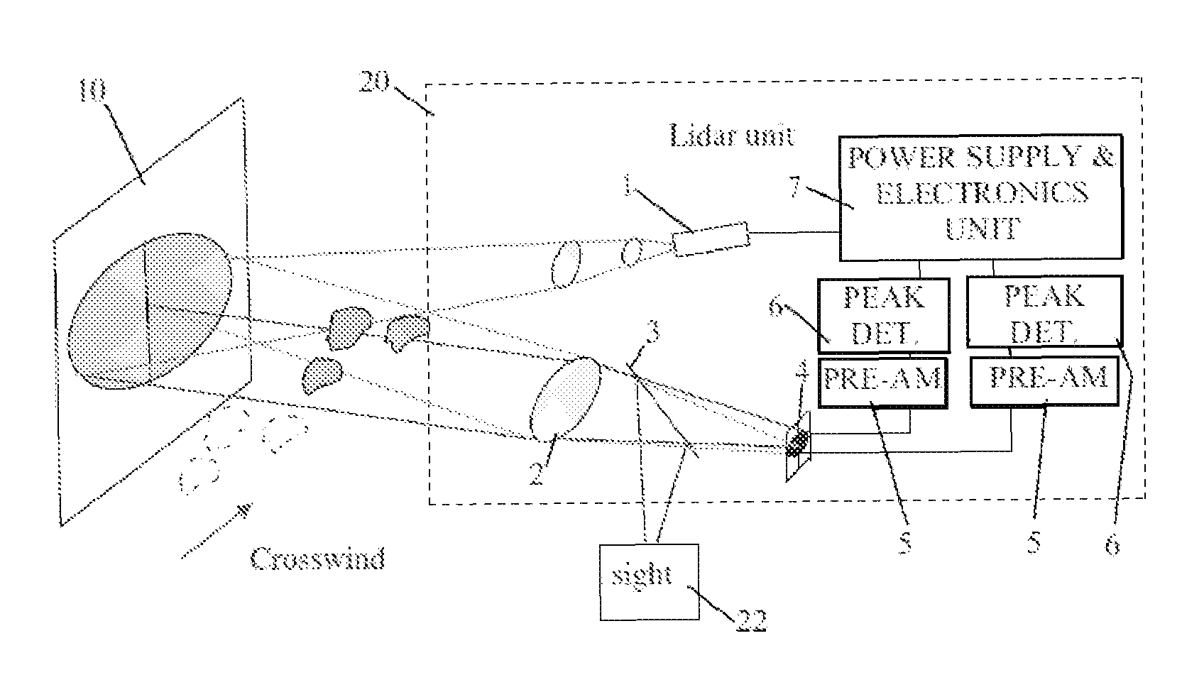
[0011]Reference is now made to FIG. 1, which illustrates a Fire Control System (FCS), constructed and operative in accordance with an embodiment of the present invention.

[0012]The FCS may comprise a LIDAR (laser identification, detecting and ranging) unit 20 and a night-and-day sight unit 22.

[0013]The LIDAR 20 may comprise an eye safe laser 1 (e.g., λ=1.54 μm), which may transmit short pulses at a 1 kHz rep-rate, and which may include transmitter optics for beam collimating (for example, with a divergence of 300 μRad) a beam which is transmitted to a target 10. (The invention is not limited to these exemplary values.) A collecting lens 2 may be provided with a wide bandpass, which is adapted to receive beams returning from the target 10. The collecting lens 2 may be correlated to the night-and-day sight unit 22 as well as to the wavelength of the laser. A dichroic beam splitter 3 with a narrow band pass (which may be adapted to the wavelength of the laser) may send the beam to the n...


PUM


Abstract

A fire control system that includes an array of photodiode elements. For each element of the photodiode array, there is a specific optical path in the atmosphere leading from the laser to a target and back from the target to the element. Accordingly, each element of the detector array can be regarded as if illuminated by a distinct light source. For short time periods (in the range of tens to hundreds of milliseconds) the shape or spatial distribution of the refractive-index irregularities does not significantly change, and the irregularities drift with the atmospheric wind. By measuring the signal fluctuations by any element of the photodiode array, it is possible to compute the crosswind velocity. By comparing signal fluctuations patterns of two or more elements it is possible to define the wind direction and to determine the turbulence strength value.

Description

FIELD OF THE INVENTION[0001]The present invention is related to methods for the fire control of flat trajectory weapons, and particularly to methods for compensating for deflections due to winds.BACKGROUND OF THE INVENTION[0002]U.S. Pat. No. 6,247,259 to Tsadka, et al., assigned to the present assignee, describes a method for the fire control of flat trajectory weapons, which comprises the steps of measuring the target range and cross wind velocity along the intended projectile trajectory prior to firing the weapon and, using the know ballistic equations of the projectile, determining the expected vertical and horizontal deflection of the projectile and adjusting the weapon sight to compensate for said deflections.[0003]More specifically, the method of U.S. Pat. No. 6,247,259 comprises, prior to firing the weapon, the steps of generating a laser beam at the firing position, receiving the beam reflected by the desired target, determining the target range by measuring the time lag bet...

Claims


Application Information

Patent Timeline
Patent Type & Authority Patents(United States)
IPC IPC(8): F41G3/08G01S17/88G01S17/95
CPCF41G1/44G01S17/88F41G3/08G01S17/95Y02A90/10
Inventor SHAPIRA, JOSEPHZMORA, HAGAI
Owner STATE OF ISRAEL - SOREQ NUCLEAR RES CENT
Why Eureka
Try Eureka