
Dynamic voltage scaling

a voltage scaling and dynamic technology, applied in the direction of liquid/fluent solid measurement, generating/distributing signals, instruments, etc., can solve the problems of increasing power consumption, limiting the ability to produce smaller, lighter devices, and suffering from relatively low percentage of productive processing cycles, so as to reduce power dissipation requirements, prolong battery life, and compact packaging of portable electronic devices

Active Publication Date: 2010-06-15
NVIDIA CORP
View PDF118 Cites 29 Cited by
  • Summary
  • Abstract
  • Description
  • Claims
  • Application Information

AI Technical Summary

Benefits of technology

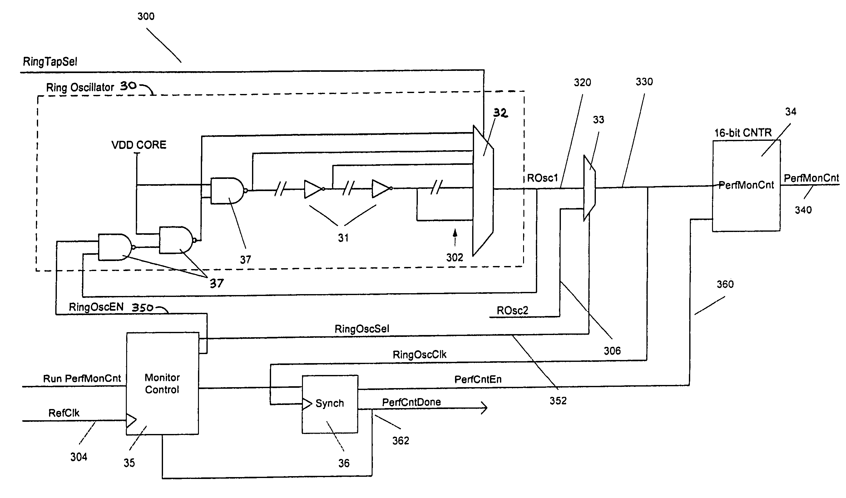
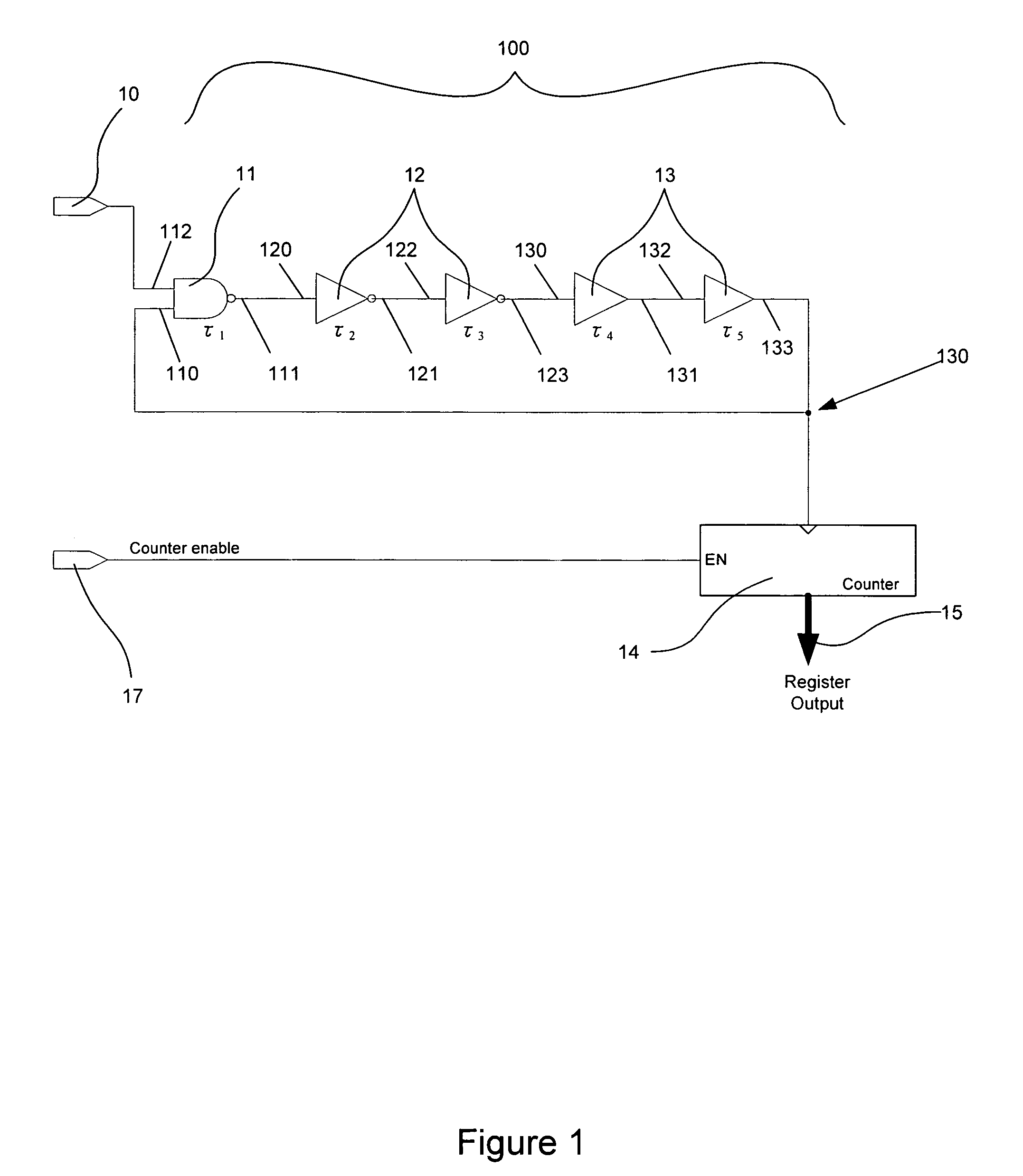
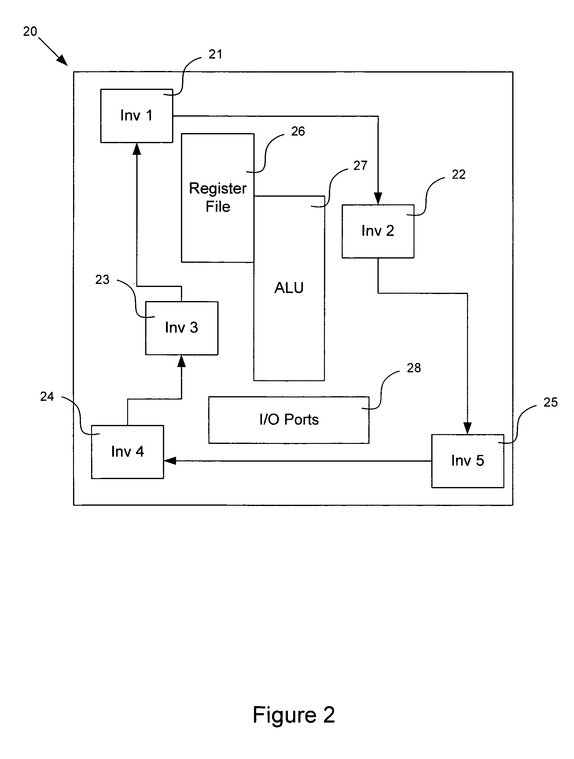
[0007]The present invention provides an apparatus and method for dynamically controlling the operating voltage of an IC device and minimize power consumption while meeting changing application requirements for operating frequency. The present invention provides an apparatus in which the operating voltage of the device can be dynamically adjusted permitting applications to vary frequency of operation of the device sufficient to meet processing needs. Thus, the apparatus may provide a minimum voltage for a selected maximum frequency, thereby minimizing power consumption over a wide range of operating frequencies.
[0009]By providing control over the operating voltage and an ability to measure and determine the maximum operating frequency of a device under any given operating conditions, the present invention may be used to reduce power dissipation requirements, prolong battery life and provide for more compact packaging of portable electronic devices.

Problems solved by technology

Increased power consumption necessitates the use of larger power supplies and more efficient cooling systems and is particularly problematic in portable, handheld devices.
Increased power typically is resolved by providing more powerful batteries and cooling requirements thereby limiting the ability to produce smaller, lighter devices.
Many current systems are designed to accommodate a highest anticipated frequency of operation and suffer from relatively low percentage of productive processing cycles because processors in the systems are idle for large portions of time.
Other current systems compromise performance to achieve lower power consumption.

Method used


Image

  • Dynamic voltage scaling
  • Dynamic voltage scaling
  • Dynamic voltage scaling

Examples


Embodiment Construction

[0020]Embodiments of the present invention will now be described in detail with reference to the drawings, which are provided as illustrative examples so as to enable those skilled in the art to practice the invention. Notably, the figures and examples below are not meant to limit the scope of the present invention. Where certain elements of these embodiments can be partially or fully implemented using known components, only those portions of such known components that are necessary for an understanding of the present invention will be described, and detailed descriptions of other portions of such known components will be omitted so as not to obscure the invention. Further, the present invention encompasses present and future known equivalents to the components referred to herein by way of illustration.

[0021]The present invention provides an apparatus and method for optimizing the performance an electronic circuit by adjusting the voltage applied to the circuit in order to control s...


PUM


Abstract

An apparatus and method for dynamically controlling the maximum frequency of operation of the IC is provided. The invention optimizes power consumption in a device by measuring a current maximum frequency of operation and adjusting IC operating voltage to provide a desired maximum operating frequency. The invention provides an apparatus and method for controlling multiple voltages in an IC to independently adjust maximum operating frequencies for a plurality of separate portions of the IC. The invention may equally be applied to a group of ICs. The invention further provides a method for calibrating an IC. Thus, the apparatus facilitates the operation of an IC at a minimum voltage for a selected maximum frequency, thereby minimizing power consumption overall a wide range of operating frequencies.

Description

BACKGROUND OF THE INVENTION[0001]1. Field of the Invention[0002]The present invention relates to power consumption within an Integrated Circuit (“IC”). The present invention more particularly relates to optimization techniques to control power consumption within an IC.[0003]2. Description of Related Art[0004]Power consumption in integrated circuit (“IC”) devices, including application specific IC (“ASIC”) devices and system-on-chip (“SOC”) devices, is dependent on both voltage and frequency. Increased power consumption necessitates the use of larger power supplies and more efficient cooling systems and is particularly problematic in portable, handheld devices. Increased power typically is resolved by providing more powerful batteries and cooling requirements thereby limiting the ability to produce smaller, lighter devices.[0005]Many current systems are designed to accommodate a highest anticipated frequency of operation and suffer from relatively low percentage of productive process...

Claims


Application Information

Patent Timeline
Patent Type & Authority Patents(United States)
IPC IPC(8): G06F1/04
CPCG06F1/3203Y02B60/1217Y02D10/00
Inventor KRISHNAN, MUSARAVAKKAM SAMARAM
Owner NVIDIA CORP
Learn More