
Combined H.450.2 and SIP call transfer

a call transfer and call technology, applied in the field of combined h.450.2 and sip call transfer, can solve the problems of difficult development of an architecture that facilitates communication services in networks relying on such multiple existing protocols, inefficient circuit design between all calling and called parties, etc., and achieve the effect of improving call setup signaling

Inactive Publication Date: 2010-06-15
AMERICAN TELEPHONE & TELEGRAPH CO
View PDF14 Cites 8 Cited by
  • Summary
  • Abstract
  • Description
  • Claims
  • Application Information

AI Technical Summary

Benefits of technology

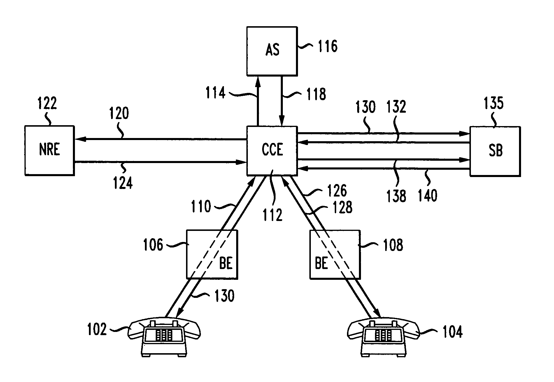
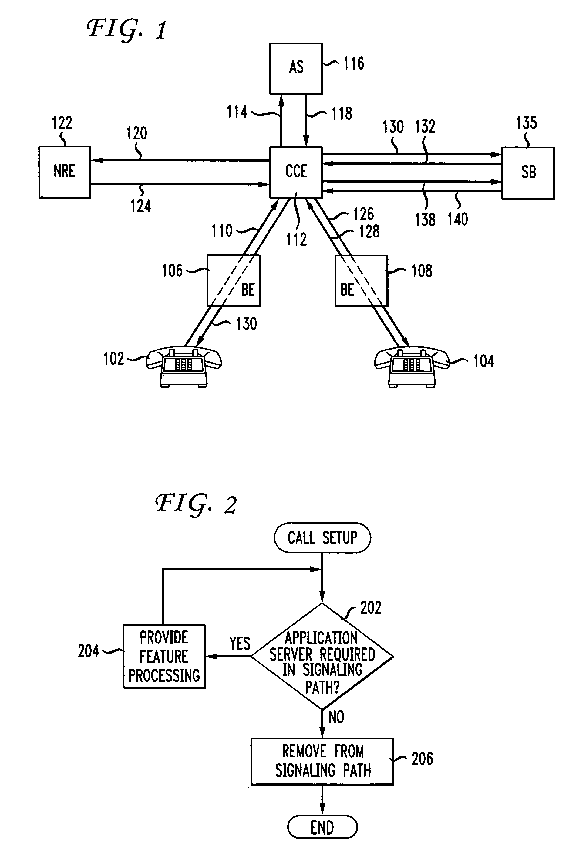
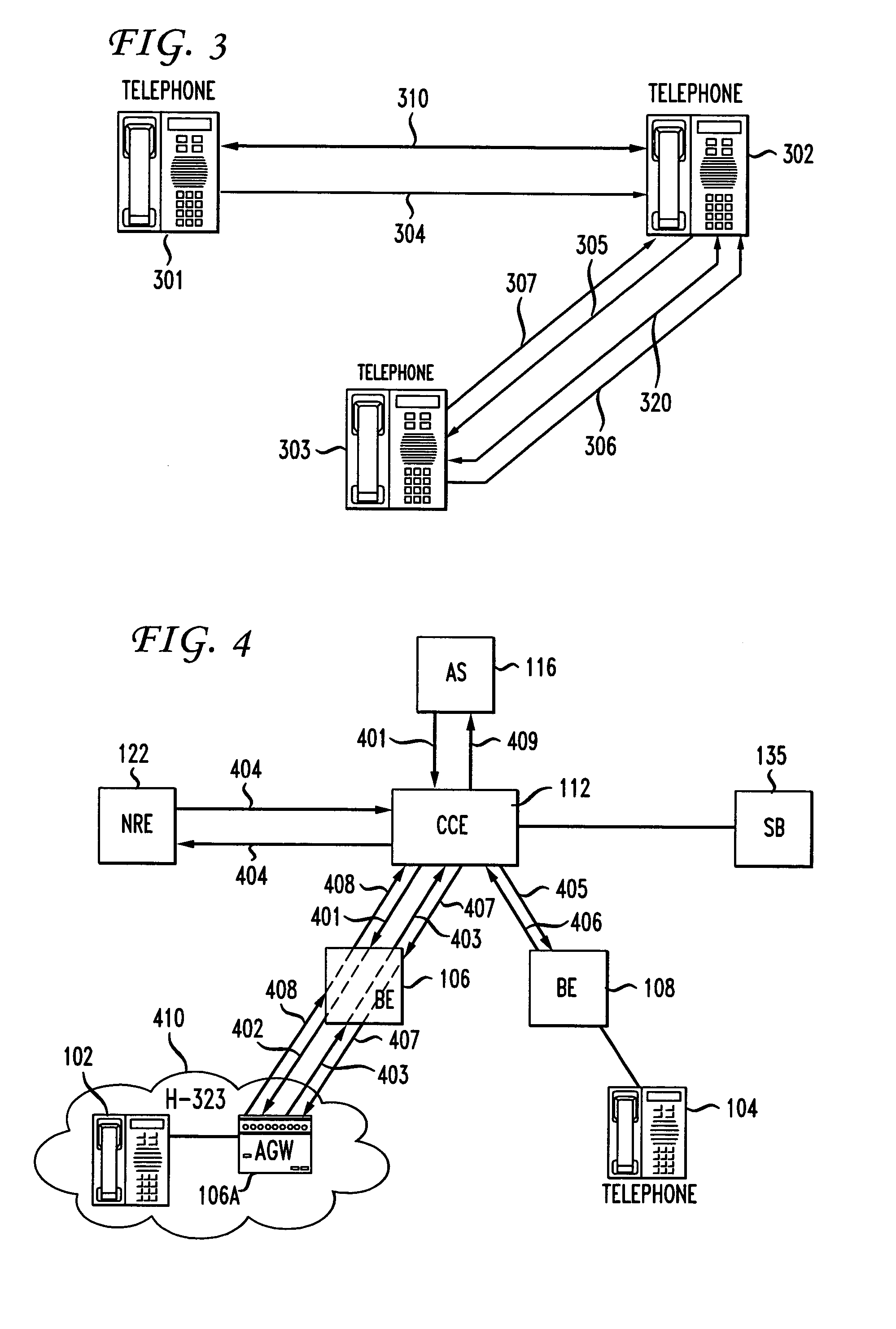
[0008]The present invention improves call setup signaling in an internet protocol network. In accordance with one embodiment of the principles of the invention, advanced features in a core SIP network are supported, even when the calling party is in a network operating in accordance with the H.323 protocol. In particular, after processing the calls by collecting information associated with such features, a REFER message is sent by an application server to an ingress border element associated with the calling party. The ingress border element then sends an H.450.2 FACILITY message containing the information in the SIP REFER message to an application gateway associated with the calling party. Upon receiving a SETUP message from the application gateway, the ingress border element then translates that SETUP message into a SIP INVITE message to establish the call.

Problems solved by technology

However, the dedication of a circuit between all calling and called parties is frequently inefficient because such dedicated circuits provide more bandwidth than is necessary.
However, while SIP-based telecommunications networks are advantageous, not all networks and components support SIP—many such networks, for example, still rely on the H.323 standard which uses different protocols.
Developing an architecture that facilitates communication services in networks relying on such multiple existing protocols is difficult.
This difficulty arises because, as discussed above, different call control / signaling protocols use different signaling mechanisms and messages that are not recognized by other protocols.

Method used


Image

  • Combined H.450.2 and SIP call transfer
  • Combined H.450.2 and SIP call transfer
  • Combined H.450.2 and SIP call transfer

Examples


Embodiment Construction

[0015]FIG. 1 shows an IP network in which one embodiment of the present invention may be implemented. The network utilizes the Session Initiation Protocol (SIP) in order to set up connections (e.g., VoIP calls) between users. As discussed previously, SIP is a well known application-layer control protocol used to establish, modify and terminate sessions such as IP telephony calls. SIP is described in detail in Internet Engineering Task Force (IETF) Request for Comments (RFC) 3261; SIP: Session Initiation Protocol; J. Rosenberg, H. Schulzrinne, G. Camarillo, A. Johnston, J. Peterson, R. Sparks, M. Handley, E. Schooler; June 2002, which is incorporated by reference herein. The details of SIP will not be described herein, as the protocol is well known to those skilled in the art. The protocol will be described only insofar as necessary for an understanding of the present invention.

[0016]With reference to FIG. 1, it is to be understood that the network elements shown in FIG. 1 are logica...


PUM


Abstract

A method for supporting advanced features in a core SIP network when the calling party is in a network operating with the H.323 protocol is disclosed. Specifically, after processing the calls by collecting information associated with the advanced features, a REFER message is sent by an application server to an ingress border element associated with the calling party. The ingress border element then sends an H.450.2 FACILITY message containing the information in the SIP REFER message to an application gateway associated with the calling party. Upon receiving a SETUP message from the application gateway, the ingress border element then translates that SETUP message into a SIP INVITE message to establish the call.

Description

[0001]This patent application claims the benefit of U.S. Provisional Application No. 60 / 678,061, filed May 5, 2005, which is hereby incorporated by reference herein in its entirety.BACKGROUND OF THE INVENTION[0002]The conventional Public Switched Telephone Network (PSTN) is a circuit switched network in which calls are assigned dedicated circuits during the duration of the call. Such networks are well known in the art, and service providers have developed various services which may be provided to subscribers via such a conventional circuit switched network.[0003]Recently, data packet networks, such as local area networks (LAN) and wide area networks (WAN) have become more prevalent. These data packet networks operate in accordance with the internet protocol (IP) and such networks are referred to as IP networks. The popularity of IP networks has created an interest in providing voice and related services over IP networks.[0004]Conventional PSTN voice services dedicate a circuit conne...

Claims


Application Information

Patent Timeline
Patent Type & Authority Patents(United States)
IPC IPC(8): H04L12/66H04L12/28
CPCH04L29/06027H04L65/1033H04M3/58H04L65/1006H04L65/1063H04L65/1009H04L65/1069H04L65/104H04L65/1106H04L65/1104H04L65/1101
Inventor IBEZIM, JAMESRUPERT, AMYSAMARASINGHE, HARISH
Owner AMERICAN TELEPHONE & TELEGRAPH CO
Learn More