
Method, system, and compositions for cell counting and analysis

a applied in the field of cell counting and composition technology, can solve the problems of limiting the widespread use of such markers, the current availability of analyzers for such markers, and the involvement of specialized personnel, and achieves the effects of efficient detection and counting, low cost, and rapid analysis

Active Publication Date: 2010-06-15
BECTON DICKINSON & CO
View PDF55 Cites 125 Cited by
  • Summary
  • Abstract
  • Description
  • Claims
  • Application Information

AI Technical Summary

Benefits of technology

The system enables facile and flexible measurements of cellular markers in blood, overcoming the limitations of existing technologies by providing a cost-effective, portable, and sensitive method for counting non-red blood cells and other cellular components, suitable for point-of-care applications.

Problems solved by technology

There is significant interest in measuring cellular markers in point-of-care devices, but cellular markers typically require some form of imaging or a fluidics system in order to make cell-specific measurements, thereby adding a significant technical challenge over that posed by the measurement of molecular markers, e.g. Shapiro, Cytometry A, 60A: 115-124 (2004); Shapiro et al, Cytometry A, 69A: 620-630 (2006); Rodriquez et al, PLOS Medicine, 2(7): e182 (2005); Janossy et al, Clinical Cytometry, 50: 78-85 (2002); Toner et al, Annu. Rev. Biomed. Eng., 7: 77-103 (2005); and the like.
Unfortunately, currently available analyzers for such markers suffer from one or more drawbacks that limit their widespread use, including complex preparation steps involving separation and / or cell lysis, involvement of specialized personnel, lack of portability, high cost, lack of sensitivity, and the like.

Method used


Image

  • Method, system, and compositions for cell counting and analysis
  • Method, system, and compositions for cell counting and analysis
  • Method, system, and compositions for cell counting and analysis

Examples


example

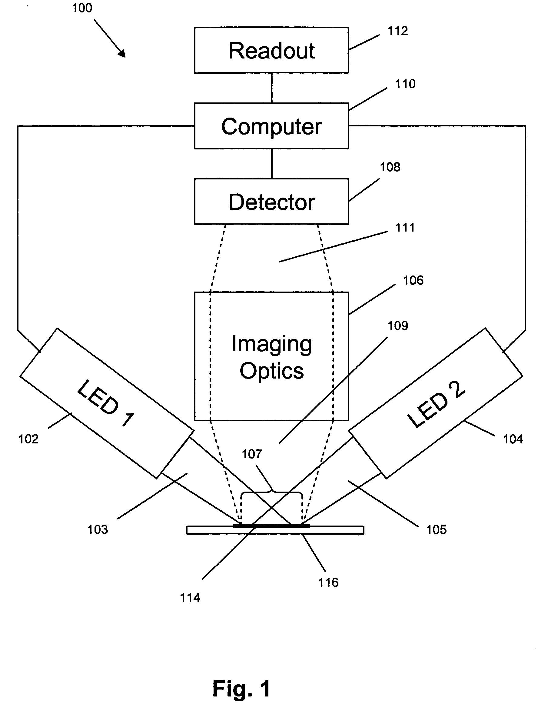
[0040]In this example, an imaging system for use with the invention was constructed and tested by counting cells or particles in various samples. The system had a design that followed that illustrated in FIG. 1. Two different grey scale cameras were employed as detectors. The first was a Sensovation Samba EZ140 TC-cooled (20° C. below ambient) camera with 1392×1024 pixels with square 6.45 um pixel. The second camera was a Point Grey Research Dragonfly2 industrial vision camera with 1024×768 square (4.65 um) pixels. Either of two imaging lens designs was used. One design was a pair of doublet spherical lenses with the excitation filter positioned between them. This system possessed a relatively high N.A. (˜0.33) and worked well for fields of view up to about 2 mm. Beyond this distance, astigmatic distortion is noticeable and increases rapidly as image field increased. To address this condition, a second lens setup was employed. This was a commercial camera lens (Nikon 18-55 mm f / 3.5-...


PUM

PropertyMeasurementUnit
wavelength rangeaaaaaaaaaa
depthaaaaaaaaaa
wavelengthsaaaaaaaaaa

Abstract

The present invention provides a low cost imaged-based system for detecting, measuring and / or counting labeled features of biological samples, particularly blood specimens. In one aspect, the invention includes a system for imaging multiple features of a specimen that includes one or more light sources capable of successively generating illumination beams each having a distinct wavelength band and a plurality of differentially excitable labels capable of labeling a specimen comprising multiple features, such that each different feature is labeled with a different differentially excitable label. System of the invention may further include a controller operationally associated with the one or more light sources for successively directing illumination beams onto the specimen so that each of the different differentially excitable labels is successively caused to emit an optical signal within the same wavelength band, an optical system capable of collecting such emitted optical signals and forming successive images corresponding to the labeled features of the specimen on a light-responsive surface to form successive sets of image data thereof, and a disposable cuvette for collection and optical analysis of non-red blood cells.

Description

[0001]This application claims priority from U.S. provisional applications 60 / 897,618 filed Jan. 26, 2007 and 60 / 995,811 filed Sep. 28, 2007, each of which is hereby incorporated by reference in its entirety.BACKGROUND[0002]Point-of-care testing and the search for effective biomarkers are important themes in biomedical research, e.g. Holland et al, Curr. Opin. Microbiol., 8: 504-509 (2005); Yager et al, Nature, 442: 412-418 (2006); Frank et al, Nature Reviews Drug Discovery, 2: 566-580 (2003); Sidransky, Nature Reviews Drug Discovery, 2: 210-218 (2002). Both endeavors are meant to improve the access and effectiveness of healthcare while reducing its costs. Point-of-care testing is analytical testing performed outside a central laboratory using a device that can be easily transported to the vicinity of the patient and that can be operated under field conditions without highly specialized personnel. In many acute care medical and bio-defense monitoring applications, rapid sample proces...

Claims


Application Information

Patent Timeline
Patent Type & Authority Patents(United States)
IPC IPC(8): G01N1/10G01N33/48
CPCB01L3/502761B01L3/502715G01N21/0303G01N21/6428G01N21/6456G01N33/5094B01L2300/0822G01N15/1434G01N15/1463G01N33/49G01N2021/0321G01N2021/0325G01N2021/0346G01N2021/6419G01N2021/6441B01L2200/0684G01N2015/1006G01N15/1459G01N15/1433
Inventor GOLDBERG, EDWARD MICHAEL
Owner BECTON DICKINSON & CO
Learn More