
Papermachine clothing

a paper machine and clothing technology, applied in the field of fabric, can solve the problems of unfavorable paper quality, undesired change in the permeability of the fabric, so as to achieve uniform permeability of the overall fabric, influence the paper quality, and constant paper quality

Inactive Publication Date: 2010-06-01
VOITH PATENT GMBH
View PDF15 Cites 0 Cited by
  • Summary
  • Abstract
  • Description
  • Claims
  • Application Information

AI Technical Summary

Benefits of technology

The present invention provides a fabric for a paper making machine that has a constant permeability during its lifetime. This is achieved by introducing a hinge member into each connecting channel of the fabric and interconnecting adjacent coil members with the hinge member. A stuffer material is introduced into each coil member and a stuffer channel is formed within each coil member. The stuffer material is introduced into the fabric and fills the spaces between the coil members, hinge members, and stuffer members. The stuffer material can be a polymeric resin and can be applied to both sides of the fabric or only one side. The stuffer material can be applied to generate a uniform distribution or a region of higher or lower permeability. This fabric design helps to improve the quality of the produced paper and ensures a stable paper making process.

Problems solved by technology

One problem with such a fabric is that the tension applied to the fabric during the paper making process in a paper machine may differ from the one as applied during the heat setting process.
Particularly when the tension applied during the paper making process is substantially higher than the tension applied during the heat setting process, there occurs a stretching of the fabric leading to an undesired change in the permeability.
One problem of such a fabric is that these fabrics, after having been used in a paper making process, often are cleaned by means of a jet of high pressure water or air or steam directed against the fabric surface in order to remove contaminants.
Such a high pressure jet directed to the fabric surface leads to the problem of dislodgement and removal of foam material such that again there occurs a change in the permeability of the fabric.

Method used


Image

  • Papermachine clothing
  • Papermachine clothing
  • Papermachine clothing

Examples


Embodiment Construction

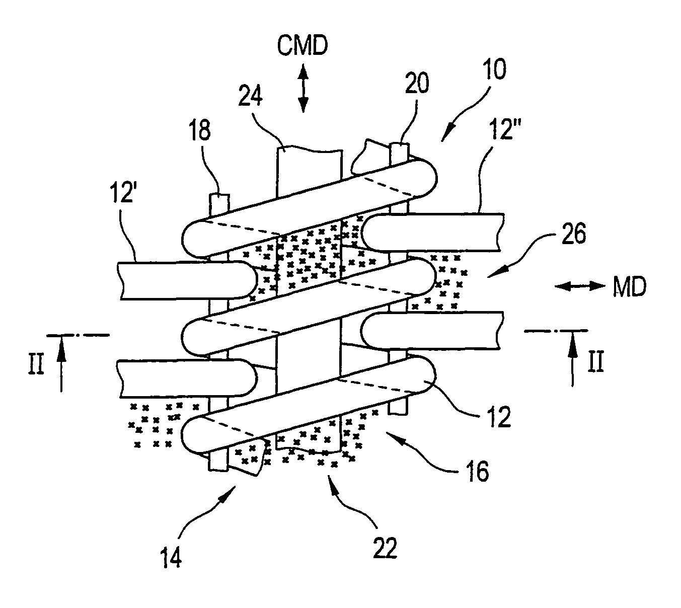
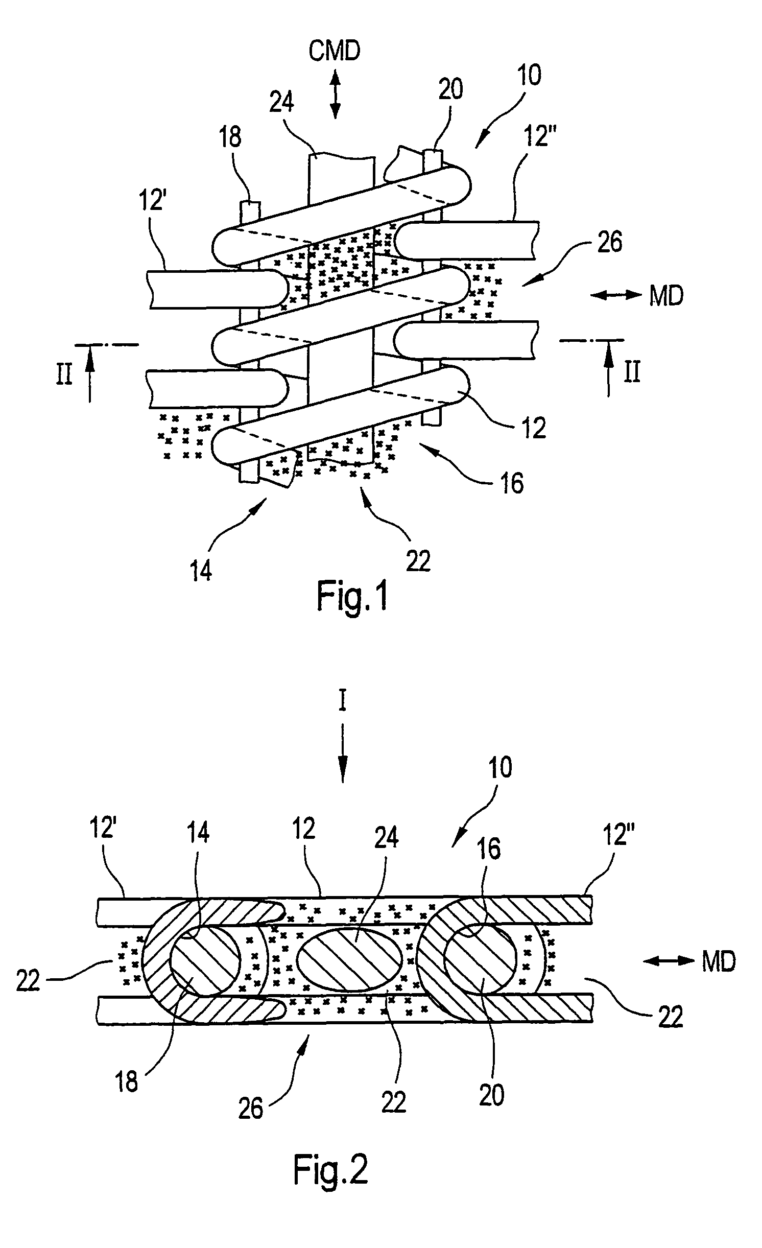
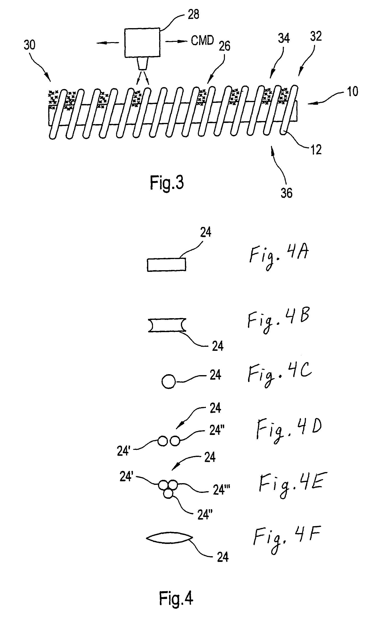
[0028]Referring now to the drawings, and more particularly to FIGS. 1 and 2, there is shown a portion of a fabric 10 of the present invention. This fabric 10 for example can be used in the drying section of a paper making machine and in this case constitutes an endless belt.

[0029]The fabric 10 includes a plurality of helically wound coil members 12, 12′, 12″ which are arranged such as to extend in a cross machine direction CMD with their longitudinal axes. Immediately adjacent coil members 12, 12′, and 12″ are arranged in an intermeshing manner. As can be seen from FIG. 1, for example the windings of coil members 12′ and 12″ engage the gaps between the windings of coil member 12 and vice versa. By providing such a mutually intermeshing arrangement of adjacent coil members 12, 12′, and 12″, in the regions of engagement there are formed connecting channels 14, 16. As can be seen in FIG. 2, the connecting channel 14 is defined by both of the coil members 12 and 12′, whereas the connect...


PUM

PropertyMeasurementUnit
operating pressureaaaaaaaaaa
permeableaaaaaaaaaa
densityaaaaaaaaaa

Abstract

A fabric, in particular for a paper making machine, includes a plurality of helically wound coil members arranged side by side with respect to each other in an intermeshing manner, such that connecting channels are formed by adjacent intermeshing coil members, a hinge member being introduced into and extending along each connecting channel for interconnecting adjacent coil members, a stuffer channel being formed within each coil member extending along and between two connecting channels associated to a respective coil member, at least a part of the stuffer channels being filled with stuffer members extending longitudinally within the stuffer channels, a stuffer material being provided at least in regions of the fabric for filling spaces formed within the fabric between the coil members, the hinge members and the stuffer members.

Description

BACKGROUND OF THE INVENTION[0001]1. Field of the Invention[0002]The present invention relates to a fabric, in particular a fabric which can be used in a paper making machine.[0003]2. Description of the Related Art[0004]One type of such fabrics used in paper making machines is the so-called stuffed spiral link fabric. Such a fabric includes a plurality of helically wound coil members extending in the cross machine direction of the fabric. These coil members are arranged such that adjacent coil members are in an intermeshing relation with respect to each other such as to generate connecting channels into which hinge members are introduced. By way of these hinge members or hinge wires, which often are referred to as pintles, the adjacent coil members are articulated with respect to each other such that a flexible endless fabric can be obtained. Within each coil member and between the two connecting channels associated to such a coil member there is a further channel which is filled wit...

Claims


Application Information

Patent Timeline
Patent Type & Authority Patents(United States)
IPC IPC(8): D21F1/10B21F27/18
CPCD21F1/0072Y10S162/903Y10T442/3146Y10T428/249922
Inventor MORTON, ANTONYPAYNE, JUSTIN ALANPONTON, DAVID STUARTJEFFREY, JOHN
Owner VOITH PATENT GMBH
Learn More