


Quick Research
Generate reliable direction feasibility study reports for your R&D in just a few steps.

Technical Q&A
Discover and master advanced knowledge NOW. Basics, ideas, possibilities, all at once.

Find Solutions
As an expert in R&D theories, this can generate solutions to your technical problems instantly.

Evaluate Feasibility
Analyze your overall solution with one click, know your potential R&D risks in advance.

Monitor Landscape
Get weekly tech updates, stay abreast of the latest tech innovations and key insights.
Photodiode array configured to increase electrical output power and optical microwave transmission system receiver utilizing the same
a technology of optical microwave transmission system and photodiode array, which is applied in the direction of photometry using electric radiation detectors, optical radiation measurement, instruments, etc., can solve the problems of insufficient utilization of optical fiber radio communication device features without electromagnetic interference, inability to downsize the device, and limited output electric power that is actually obtained, etc., to achieve the effect of high power
- Summary
- Abstract
- Description
- Claims
- Application Information
AI Technical Summary
Benefits of technology
Problems solved by technology
Method used
Image

Examples
embodiment 1
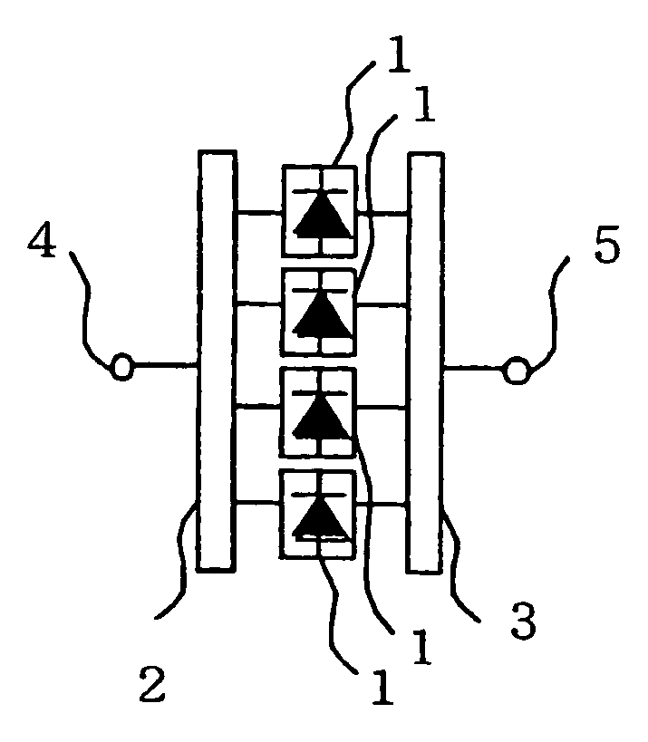
[0020]FIG. 1 is a diagram showing a photodiode according to Embodiment 1 of the present invention. As shown in FIG. 1, a plurality of photodiode elements 1 are arranged to form a photodiode array. A modulated light that has been input to a light input terminal 4 is branched by an optical branching filter circuit 2, and then input to the plurality of photodiode elements 1. Electric signals that have been detected by the photodiode elements 1 are combined together by an electric power combining circuit 3, and output from an electric output terminal 5.
[0021]Referring to FIG. 1, transmission paths of the light which is branched by the optical branching filter circuit 2 and input to the plurality of photodiode elements 1 are substantially identical in the length with each other as compared with the order of the wavelength of the modulated microwave over all of the paths.
[0022]Accordingly, the electric signals that have been detected by the plurality of photodiode elements 1 are combined ...
embodiment 2
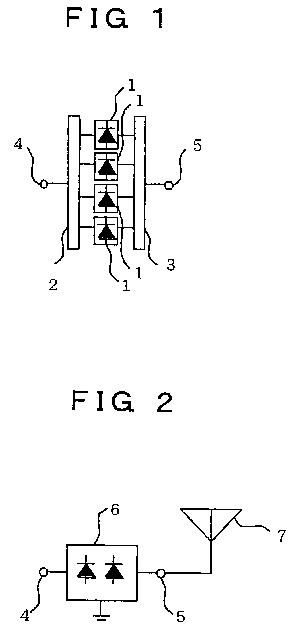
[0032]FIG. 2 is a diagram showing an optical microwave transmission receiver according to Embodiment 2 of the present invention.
[0033]In the optical microwave transmission receiver shown in FIG. 2, a photodiode array 6 having the same configuration as that in Embodiment 1 shown in FIG. 1 is input with a light modulated signal from the light input terminal 4. The light modulated signal is detected by the photodiode array 6 and output from the electric output terminal 5 as the RF electric signal. In addition, the RF electric signal is input to an antenna 7 and radiated toward a space as the electromagnetic wave from the antenna 7.
[0034]In the optical microwave transmission receiver shown in FIG. 2, the electric signal that is output from the photodiode array 6 is connected directly to the antenna 7 without being input to the amplifier circuit such as an amplifier. The reason is that the electric signal can be radiated directly from the antenna 7 since the electric power of the electri...
embodiment 3
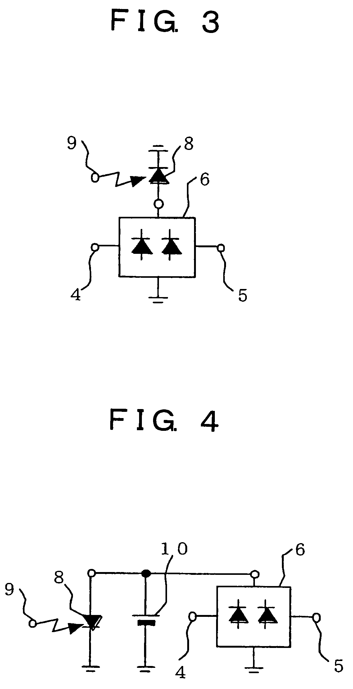
[0036]FIG. 3 is a diagram showing a photodiode array according to Embodiment 3 of the present invention. The photodiode array 6 shown in FIG. 3 detects, as in Embodiments 1 and 2, a light modulation signal that is input from the light input terminal 4, and outputs the light modulation signal from the electric output terminal 5 as the RF electric signal. In addition, the photodiode array 6 shown in FIG. 3 is connected with an electric power supply photodiode 8 via a bias.
[0037]The electric power supply photodiode 8 constitutes electric power converting means for converting the light that has been input to an electric power supply light input terminal 9 by the optical fiber into an electric energy to supply the converted electric energy to the photodiode array 6 as a bias power supply.
[0038]For that reason, the power of the photodiode itself can be supplied by light, and the photodiode that does not require at all an internal power supply or the electric power supply from the external...
PUM
 Abstract
Description
Claims
Application Information
 - R&D Engineer
- R&D Manager
- IP Professional
- Industry Leading Data Capabilities
- Powerful AI technology
- Patent DNA Extraction
Browse by: Latest US Patents, China's latest patents, Technical Efficacy Thesaurus, Application Domain, Technology Topic, Popular Technical Reports.
© 2024 PatSnap. All rights reserved.Legal|Privacy policy|Modern Slavery Act Transparency Statement|Sitemap|About US| Contact US: help@patsnap.com