Eureka AIR delivers breakthrough ideas for toughest innovation challenges, trusted by R&D personnel around the world.

Pressure-balanced, catalyzed soot filter

a filter and pressure-balance technology, applied in the field of catalyst articles, can solve the problems of shortening the useful life of catalyst compositions coated along the length of the substrate, limiting the useful life of the entire catalyst-coated wall flow substrate, and high material costs associated with platinum group metal-containing compositions, so as to reduce overall platinum group metal component material costs and reduce exhaust gas pollutants

Active Publication Date: 2010-05-25
BASF CATALYSTS LLC
View PDF10 Cites 83 Cited by
  • Summary
  • Abstract
  • Description
  • Claims
  • Application Information

AI Technical Summary

Benefits of technology

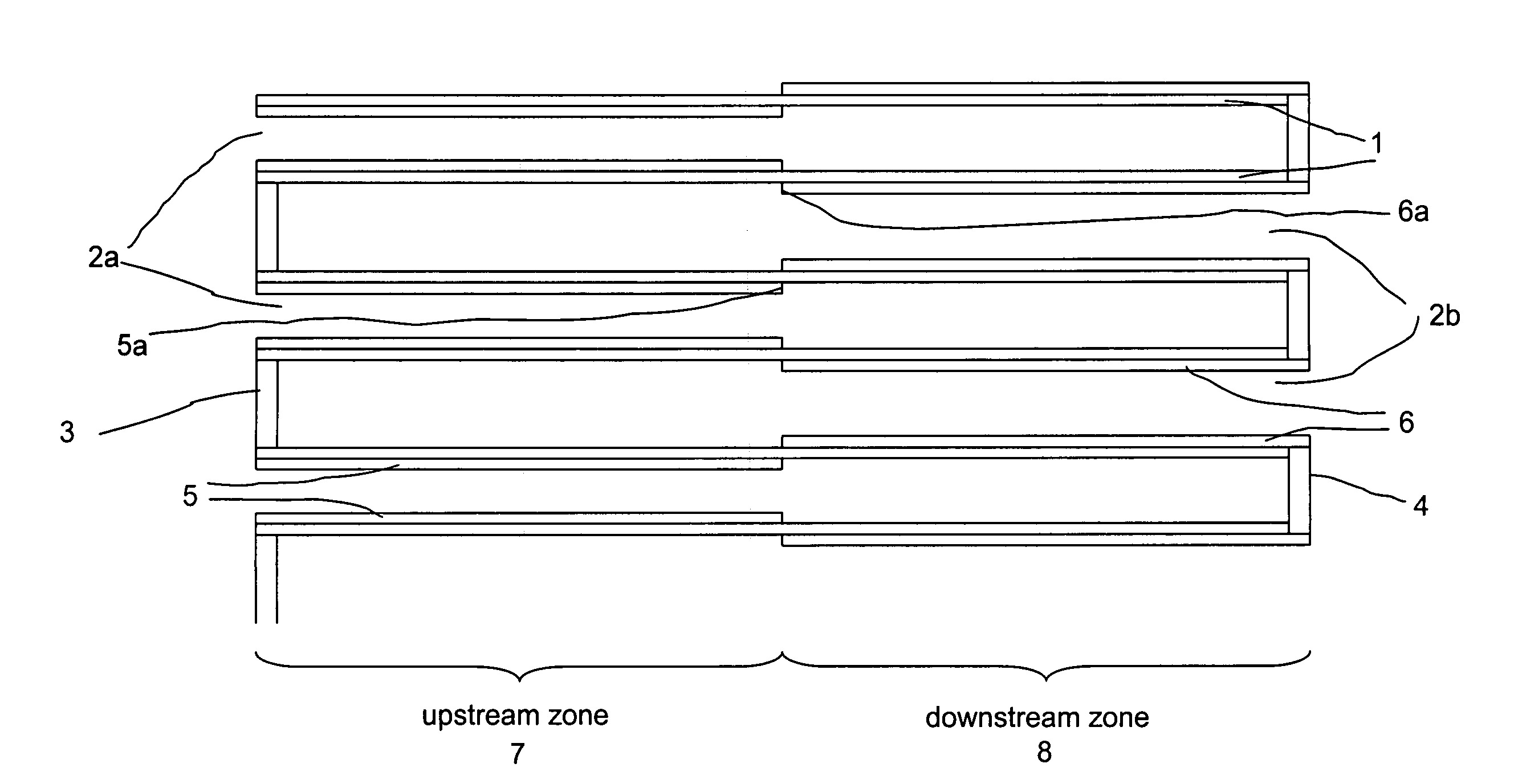
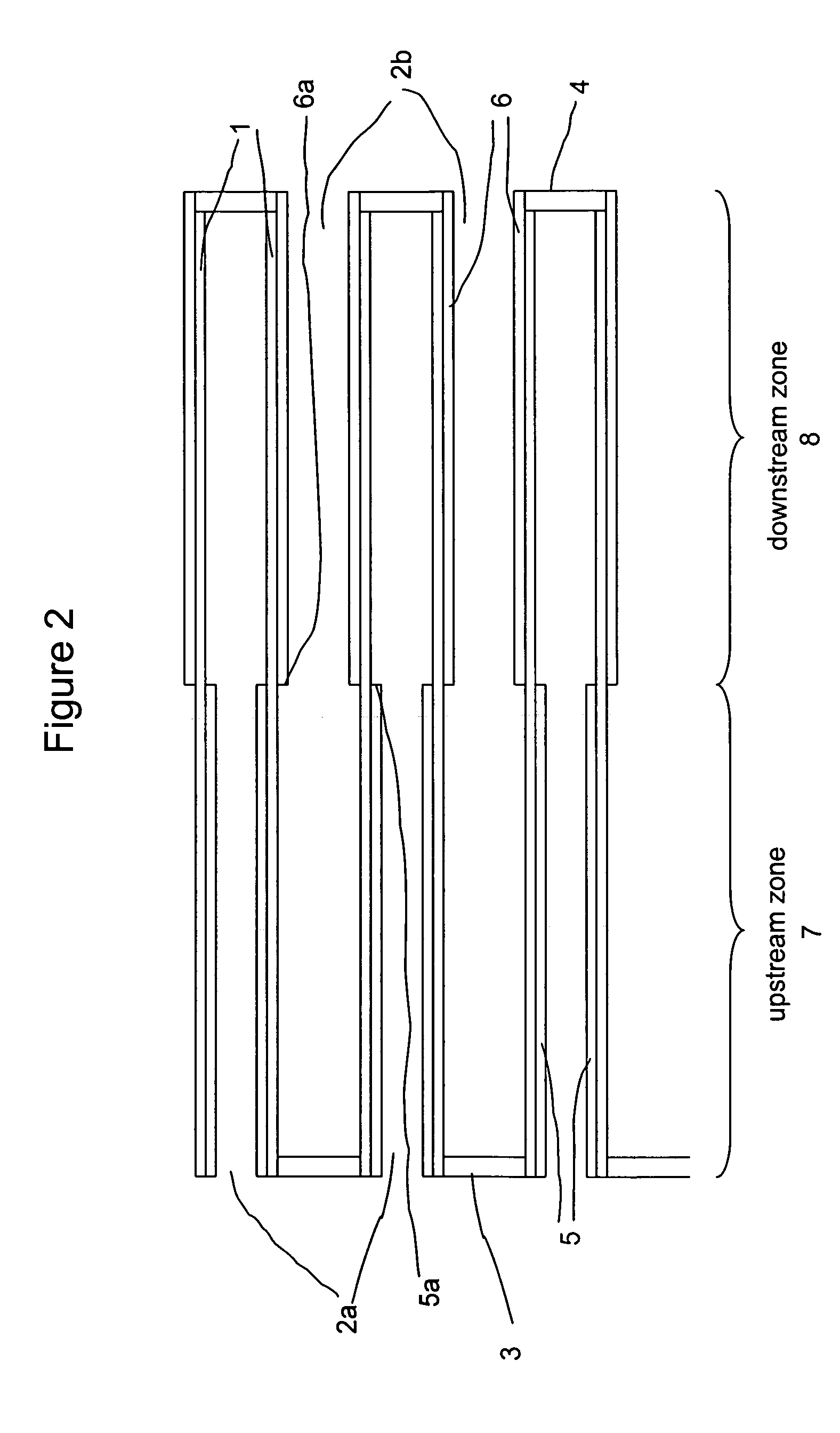
"The invention is about a catalyzed soot filter that helps to purify exhaust gas streams by reducing soot, NOx, CO, and unburned hydrocarbons. The filter has a wall flow substrate with inlet and outlet passages that have internal walls with a first inlet coating and a second inlet coating. The first inlet coating has a first inlet platinum group metal component and is present in the upstream zone, while the second inlet coating has a second inlet platinum group metal component and is present in the downstream zone. The length of the upstream and downstream zones is typically between 20% and 80% of the substrate axial length. The first and second inlet coatings can have different lengths and are typically present at concentrations of 0.1 to 1.5 g / in3 and 0.1 to 2.0 g / in3, respectively. The invention also includes a method for treating exhaust gas streams with the catalyzed soot filter."

Problems solved by technology

In coated wall flow filters, exposure to such high temperatures during regeneration events shortens the useful lifetime of the catalyst compositions coated along the length of the substrate.
Thus, the durability of the catalyst composition along the downstream segment limits the useful lifetime of the entire catalyst-coated wall flow substrate.
High material costs associated with platinum group metal-containing compositions augment the need to slow or prevent the degradation of catalyst coatings due to active regeneration events.
The cost associated with the required platinum group metal concentration is often higher than is desired.
This differential flow pattern can result in inadequate pollutant conversion.

Method used


Image

  • Pressure-balanced, catalyzed soot filter
  • Pressure-balanced, catalyzed soot filter
  • Pressure-balanced, catalyzed soot filter

Examples


example 1

Homogeneous Catalyst Coating: Reference Catalyst A

[0112]This catalyst composition was coated on a silicon carbide filter used with the intention to trap particulate matter (soot) and abate the residual hydrocarbon and CO generated in the diesel exhaust during combustion.

[0113]This catalyst coating was made by impregnating 313 g of a solution of amine-solubilized platinum hydroxide (about 17% Pt) onto 546 g of 1.5% silica alumina support (120 m2 / g) followed by fixing the Pt using acetic acid solution. This material made into a slurry of about 40% solid then milled to a particle size less than 8 microns. After milling, 1100 g of CeO2—Pr6O11—ZrO2 composite (containing 30 wt. % ceria, 10 wt. % praeseodymia, and 60 wt. % zirconia) was added to the slurry followed by zirconyl acetate (296 g at 30% ZrO2) and milled further to less than 5 microns. The slurry was then diluted to about 30% solid. The slurry was used to coat one of the walls of a silicon carbide wall flow filter substrate (dim...

example 2

Catalyst B

[0114]This soot filter had the coating design as shown in FIG. 3, and had a first inlet coating, a second inlet coating and an outlet coating.

[0115]The slurries for each of the coatings were prepared identically except for the differing concentrations of platinum and different solids content. The platinum concentrations and the solids content were adjusted to achieve the target washcoat loading for each coating. The slurries were made by impregnating the Pt salt solution onto gamma-alumina. Acetic acid was used to precipitate the Pt. The impregnated alumina was made into a slurry about 40% solids by adding water and some acetic acid. Zirconium acetate was added and the slurry was milled to an average particle size less than 5 microns. Three slurries were made based on the above procedure and each slurry was coated in the following order:

[0116]Second Inlet Coating: 100% of the inlet of the filter was coated to give a washcoat loading based on calcined weight of about 0.27 g...

example 3

Catalyst C

[0120]This soot filter had the coating design as shown in FIG. 3, and had a first inlet coating and an outlet coating.

[0121]The slurries for each of the coatings were prepared identically except for the differing concentrations of platinum and different solids content. The platinum concentrations and the solids content were adjusted to achieve the target washcoat loading for each coating. The slurries were made by impregnating the Pt salt solution onto gamma-alumina. Acetic acid was used to precipitate the Pt. The impregnated alumina was made into a slurry about 40% solids by adding water and acetic acid. Zirconium acetate was added and the slurry was milled to an average particle size less than 5 microns. Two slurries were made based on the above procedure and each slurry was coated in the following order:

[0122]First Inlet Coating: 50% of the inlet of the filter was coated to give a washcoat loading based on calcined weight of about 0.6 g / in3, a zirconia concentration of ...


PUM

PropertyMeasurementUnit
pore sizeaaaaaaaaaa
wt. %aaaaaaaaaa
temperatureaaaaaaaaaa

Abstract

The invention provides a catalyzed soot filter formed on a wall flow substrate having internal walls coated with catalyst compositions. The soot filter maintains a homogeneous flow of the exhaust gases through the internal walls of the substrate along the length of the filter due to the coating design. Both the efficiency and the durability of the catalytic function are increased over conventionally designed catalyzed soot filters. The catalyzed soot filter provides an integrated function for simultaneously treating the gaseous components of the exhaust (e.g., CO and HC) and the particulate matter deposited in the filter.

Description

[0001]The present invention relates to a catalyst article useful for the treatment of exhaust gases from diesel engines.[0002]Diesel engine exhaust is a heterogeneous mixture which contains not only gaseous emissions such as carbon monoxide (“CO”), unburned hydrocarbons (“HC”) and nitrogen oxides (“NOx”), but also condensed phase materials (liquids and solids) which constitute the so-called particulates or particulate matter. Emissions treatment systems for diesel engines must treat all of the components of the exhaust to meet emissions standards set by various regulatory agencies throughout the world.[0003]The total particulate matter emissions of diesel exhaust contain three main components. One component is the solid, dry, solid carbonaceous fraction or soot fraction. This dry carbonaceous fraction contributes to the visible soot emissions commonly associated with diesel exhaust. A second component of the particulate matter is the soluble organic fraction (“SOF”). The SOF can exi...

Claims


Application Information

Patent Timeline
Patent Type & Authority Patents(United States)
IPC IPC(8): B01D50/00
CPCB01D53/944F01N3/0222F01N3/035B01J35/0006B01J23/42B01J37/0248B01J23/40B01J23/63B01J29/068B01J35/04B01D2255/2066F01N2510/06B01D2255/1021B01D2255/407B01D2255/9155B01D2255/9022B01J35/19B01J35/56F01N3/022B01D53/94
Inventor PUNKE, ALFRED HELMUTMUELLER, TORSTEN WOLFGANGDEEBA, MICHELVOSS, KENNETH EDWINSTEGER, JOHN JOSEPHLUI, YIU KWAN
Owner BASF CATALYSTS LLC
Why Eureka
Eureka Blog
Learn More