Eureka AIR delivers breakthrough ideas for toughest innovation challenges, trusted by R&D personnel around the world.

Damping force generation system and vehicle suspension system constructed by including the same

a technology of generating system and damping force, which is applied in the direction of shock absorbers, machine supports, transportation items, etc., can solve the problems of insufficient damping force, speed, deterioration of controllability of damping force control, etc., and achieve the effect of high utility

Inactive Publication Date: 2010-05-25
TOYOTA JIDOSHA KK +1
View PDF31 Cites 106 Cited by
  • Summary
  • Abstract
  • Description
  • Claims
  • Application Information

AI Technical Summary

Benefits of technology

[0004]The recently proposed electromagnetic suspension suffers from problems such as insufficiency of the damping force and deterioration of the controllability for controlling the damping force, in an instance where the stroke motion indicated above is performed at a high speed, namely, in an instance where a speed of the stroke motion (i.e., stroke speed) is inevitably high due to unevenness of the road surface, for instance. The above problems in the high-speed motion are just a few examples of problems experienced in the electromagnetic suspension. The electromagnetic suspension in the process of development suffers from various problems and has much room for improvement. The present invention has been made in the light of the situations described above. It is therefore an object of the invention to provide an electromagnetic suspension with high utility by resolving the problems experienced in the electromagnetic suspension and to provide a damping-force generating system for realizing the electromagnetic suspension system with high utility.

Problems solved by technology

The recently proposed electromagnetic suspension suffers from problems such as insufficiency of the damping force and deterioration of the controllability for controlling the damping force, in an instance where the stroke motion indicated above is performed at a high speed, namely, in an instance where a speed of the stroke motion (i.e., stroke speed) is inevitably high due to unevenness of the road surface, for instance.
The electromagnetic suspension in the process of development suffers from various problems and has much room for improvement.

Method used


Image

  • Damping force generation system and vehicle suspension system constructed by including the same
  • Damping force generation system and vehicle suspension system constructed by including the same
  • Damping force generation system and vehicle suspension system constructed by including the same

Examples


first embodiment

1. First Embodiment

[0129]The following first embodiment relates to a damping-force generating system which employs, as a first damping-force generating device, an electromagnetic absorber device that generates a damping force based on a force of an electromagnetic motor and which also employs, as a second damping-force generating device, a hydraulic absorber device that generates a damping force based on an action of a liquid.

i) Overall Structure of Suspension System

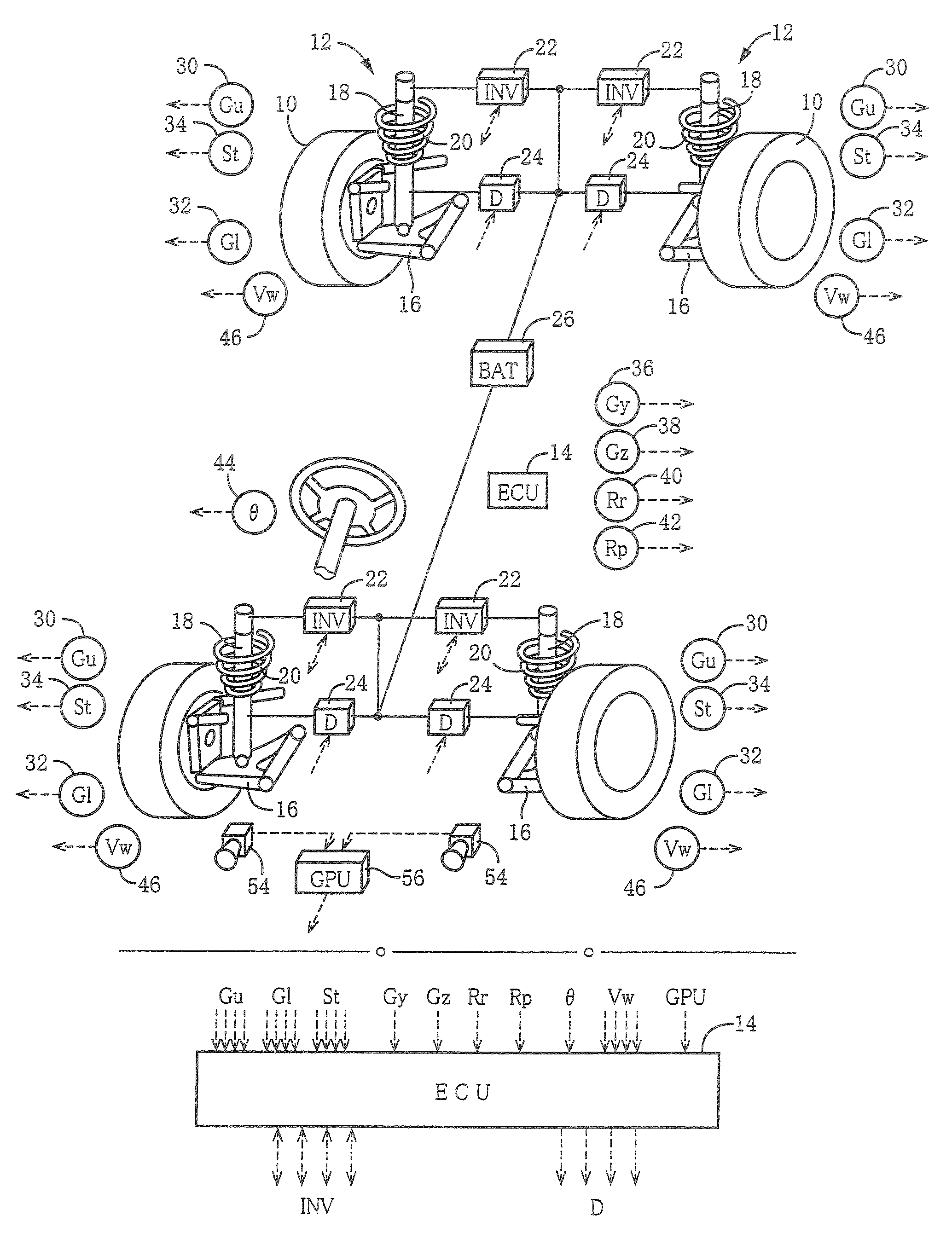
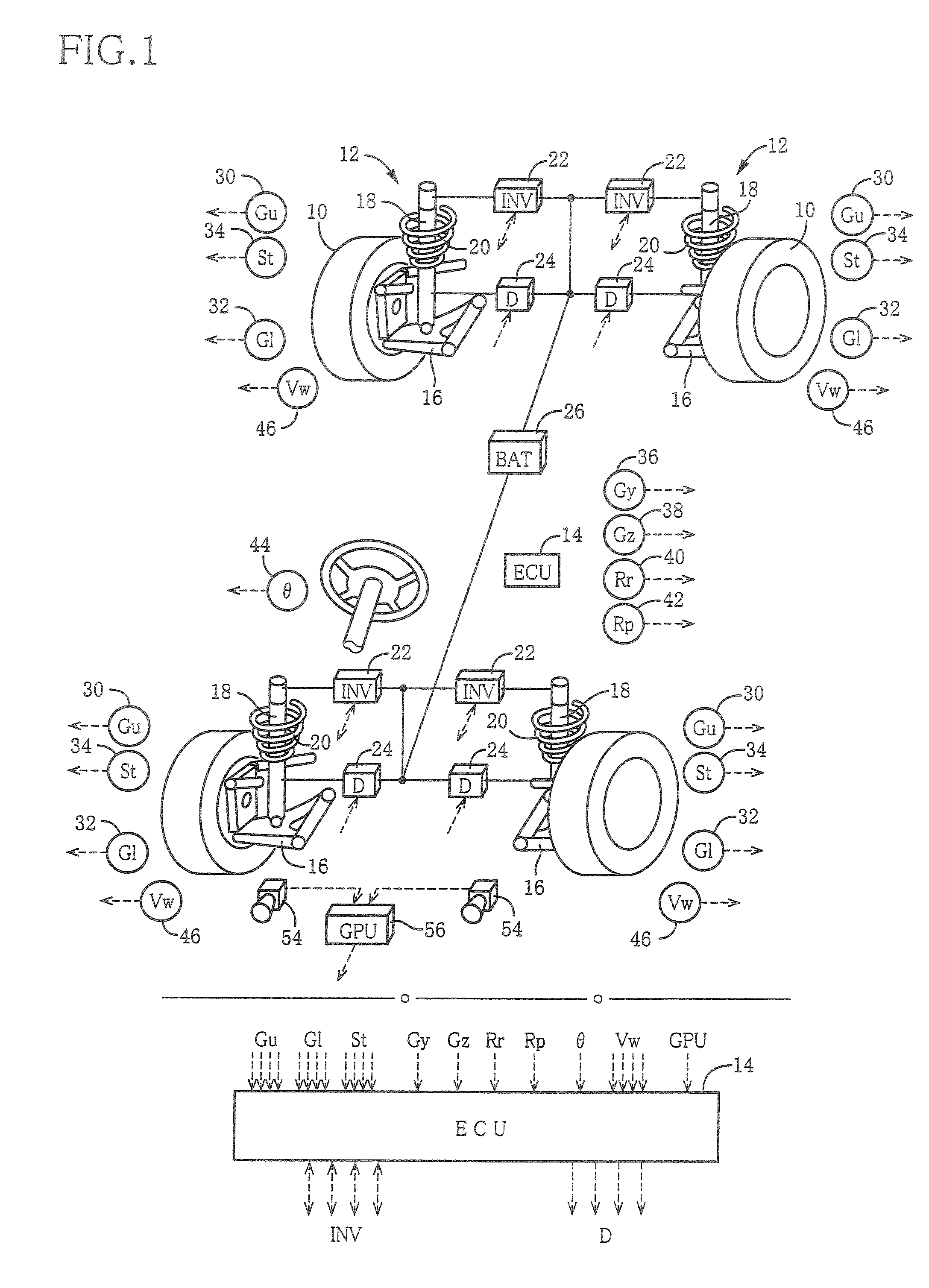
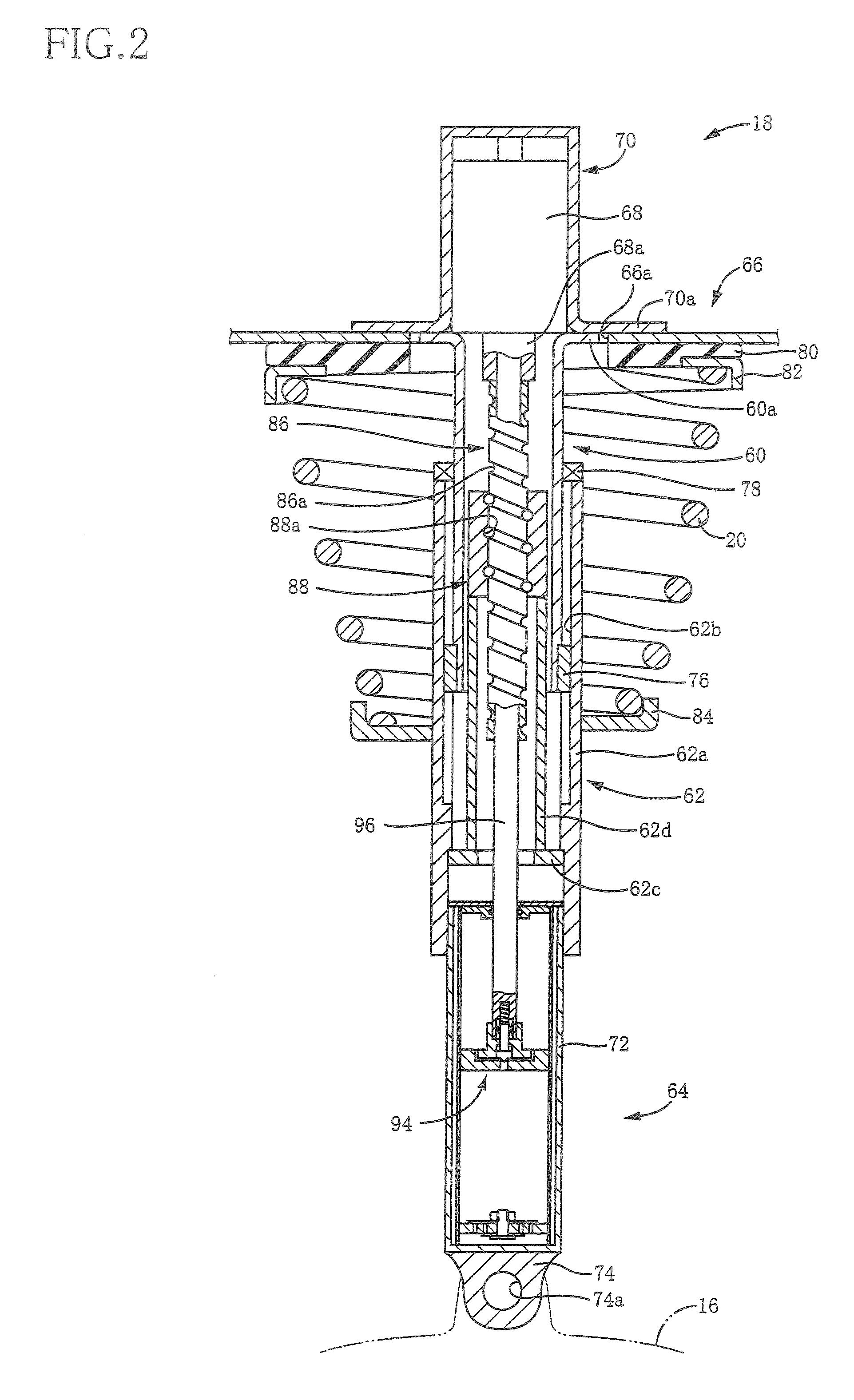
[0130]FIG. 1 schematically shows an overall structure of a suspension system for a vehicle in which is employed a damping-force generating system according to the first embodiment. The present suspension system is constituted by including four electromagnetic suspension apparatus 12 respectively for four wheels 10 (hereinafter simply referred to as “suspension apparatus 12”) and a suspension electronic control device 14 (hereinafter simply referred to as “suspension ECU 14” or “ECU 14”) as a control device for controllin...

second embodiment

2. Second Embodiment

[0176]There will be next explained a second embodiment which relates to a damping-force generating system including two electromagnetic absorber devices which respectively employ electromagnetic motors and which have mutually different damping-force characteristics, in more detail, a damping-force generating system in which the characteristics of the rotational torque of the two electromagnetic motors are different form each other. In the second embodiment and the following embodiments, the same reference numerals as used in the illustrated first embodiment are used to identify the corresponding components and a detailed explanation of which is dispensed with.

i) Overall Structure of Suspension System

[0177]A suspension system for a vehicle in which is employed a damping-force generating system according to the second embodiment has an overall structure similar to that of the system according to the illustrated first embodiment shown in FIG. 1. It is noted, however...

third embodiment

3. Third Embodiment

[0220]There will be next explained a third embodiment relating to a damping-force generating system which employs an electromagnetic absorber device and in which a variable resistor device is interposed between the electromagnetic motor of the absorber device and the power source.

i) Structure of Absorber and Overall structure of Suspension System

[0221]FIG. 25 shows an absorber 260 of a damping-force generating system according to the third embodiment. In the absorber 260, the two motors 178A, 178B of the absorber 170 shown in FIG. 15 in the second embodiment are replaced with one electromagnetic motor 262. Other portions of the absorber 260 are the same as the absorber 170, and a detailed explanation of which is not given here. Further, the overall structure of the suspension system constituted by including the present damping-force generating system is substantially the same as that of the suspension system in the second embodiment, except that one inverter 22 is...


PUM


Abstract

It is an object of the invention to improve the utility of an electromagnetic absorber system which is disposed in a suspension system of a vehicle and which generates a damping force by a generation force of a motor. The electromagnetic absorber system 18 is equipped with high-speed-motion responding means, thereby obviating an insufficiency of the damping force and a deterioration of the controllability in a high-speed stroke motion. More specifically, a hydraulic absorber 64 is provided in combination with the electromagnetic absorber system such that the hydraulic absorber 64 operates in the high-speed motion in which an electromotive force of the motor 68 exceeds a power source voltage Further, two motors having mutually different T-N characteristics are provided, and the two motors are selectively operated depending upon a stroke speed. Further, a variable resistor is interposed between the motor and the power source, and a resistance value of the variable resistor is increased in the high-speed motion to realize a decrease in a time constant of the motor, etc. Moreover, to cope with a large extent of unevenness of a road surface, an active stroke motion is performed by a drive force of the motor, thereby preventing the high-speed motion from being performed.

Description

TECHNICAL FIELD[0001]The present invention relates to a damping-force generating system which constitutes a suspension system for a vehicle and which generates a damping force with respect to a stroke motion in which a wheel and a body of the vehicle move toward and away from each other. In particular, the present invention relates to a damping-force generating system equipped with a damping-force generating device which generates a damping force that depends on a generation force generated by an electromagnetic motor and also relates to a suspension system for a vehicle constituted by including the damping-force generating system.BACKGROUND ART[0002]A conventional suspension system for a vehicle is equipped with a so-called hydraulic shock absorber by which is generated a damping force with respect to a motion of the wheel and the vehicle body toward and away from each other. Because such a motion can be considered to be a stroke motion of the wheel relative to the vehicle body, th...

Claims


Application Information

Patent Timeline
Patent Type & Authority Patents(United States)
IPC IPC(8): B60G17/016
CPCB60G15/063B60G17/06B60G17/08F16F9/466B60G2202/312B60G2202/42B60G2400/202B60G2400/82B60G2500/11B60G2600/182B60G2204/4193B60G13/14
Inventor INOUE, HIROFUMIYAMAGUCHI, TAKENARIKONDO, TAKUHIRO
Owner TOYOTA JIDOSHA KK
Why Eureka
Eureka Blog
Learn More