Linear damper

a damper and linear technology, applied in the field of moving dampers, can solve the problems of limited space, bulky and heavy door frames, and need to move in straight lines in limited space, and achieve the effect of small space, simple and inexpensive manufacturing and supply

Inactive Publication Date: 2010-05-18
ILLINOIS TOOL WORKS INC
View PDF23 Cites 5 Cited by
  • Summary
  • Abstract
  • Description
  • Claims
  • Application Information

AI Technical Summary

Benefits of technology

[0012]An advantage of the present invention is providing a linear damper that operates in a small space.
[0013]Another advantage of the present invention is providing a linear damper that is simple and inexpensive to manufacture and supply.
[0014]Still another advantage of the present invention is providing a linear damper that provides damping in one direction for movement of a rod, with little or no damping in an opposite direction of movement.
[0015]Yet another advantage of the present invention is providing a linear damper that requires little or no adjustment and can operate through many cycles of operation.
[0016]Other features and advantages of the invention will become apparent to those skilled in the art upon review of the following detailed description, claims and drawings in which like numerals are used to designate like features.

Problems solved by technology

Such console doors can be both bulky and heavy.
Movement dampers can be used to lessen the closing force from the weight of the door, thereby preventing the door or cover from falling shut forcefully, potentially causing damage.
Limited space can require straight line movement.

Method used


Image

  • Linear damper
  • Linear damper
  • Linear damper

Examples


Embodiment Construction

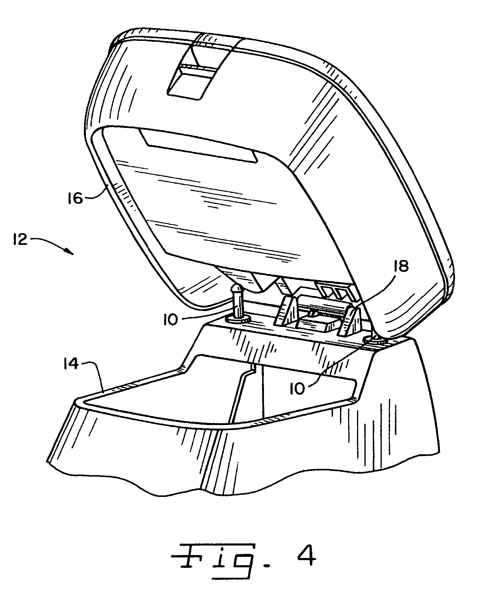
[0022]Referring now more specifically to the drawings and to FIG. 1 in particular, numeral 10 designates a linear damper in accordance with the present invention. While linear dampers of the present invention are expected to have a variety of advantageous applications and uses, one particularly advantageous use is to control the closing movement of automobile console doors. FIG. 4 illustrates an automobile console 12 having a base or bin 14 and a cover 16. Cover 16 is connected to bin 14 by a hinge 18. Two linear dampers 10 of the present invention are illustrated to control closing movement of cover 16. Console 12 is merely one example of a suitable use, and the description thereof to follow should not be considered as a limitation on the application and use of the present invention.

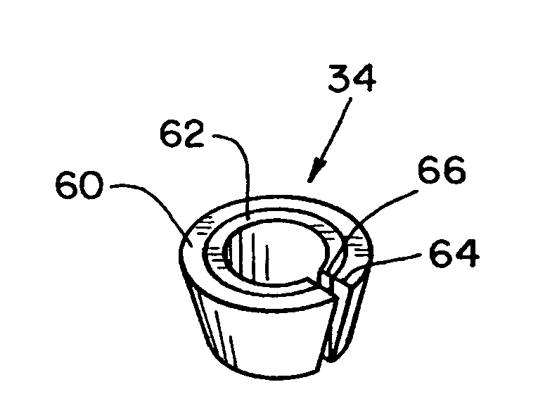
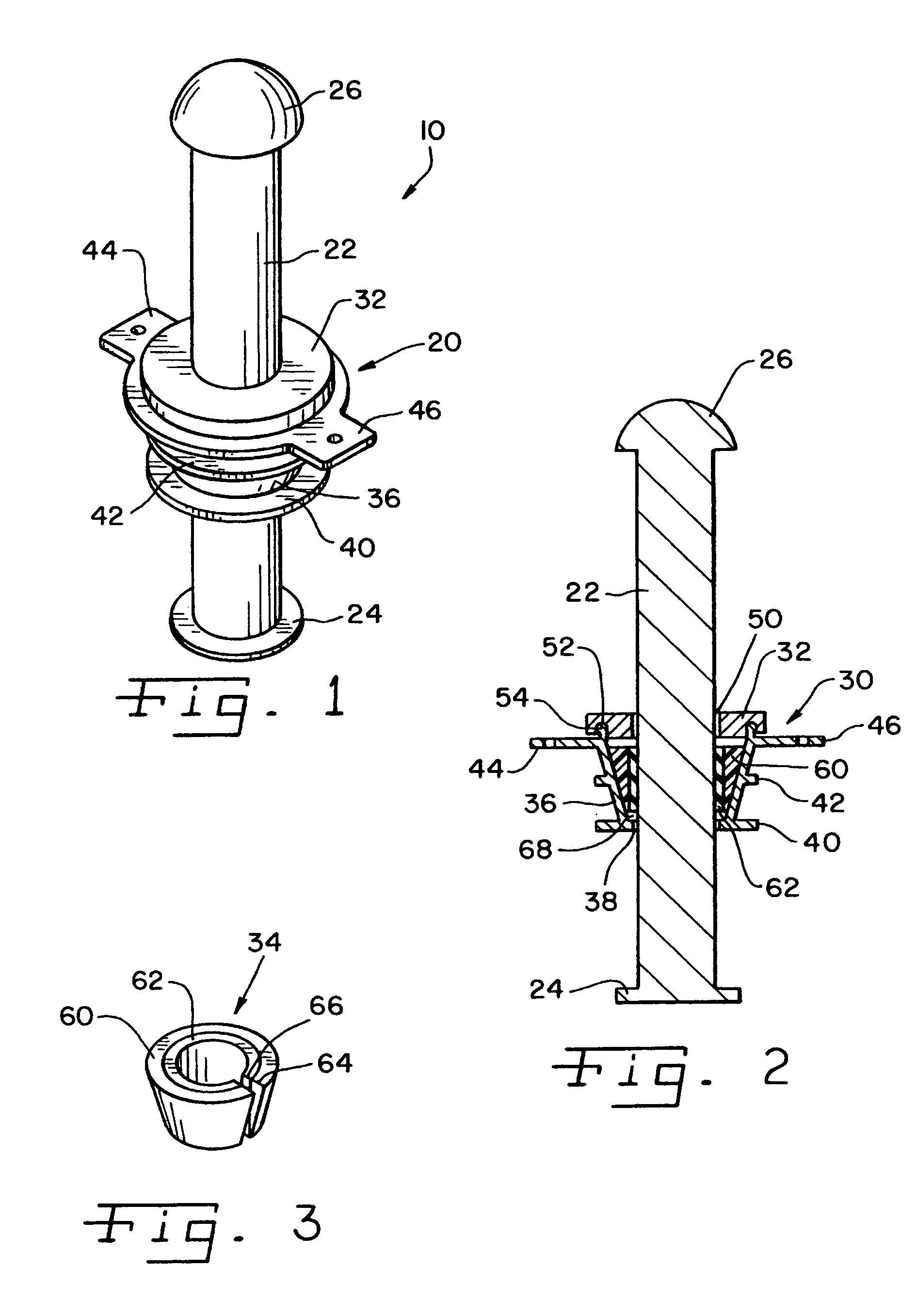
[0023]Damper 10 includes a damping assembly 20 and a rod 22 axially movable relative to damping assembly 20.

[0024]Rod 22 is a substantially linear, elongate body having a base 24 at one end thereof and ...


PUM


Abstract

A linear damper includes a conical housing with a friction cone in the housing and a rod extending therethrough and axially moveable relative thereto. The friction cone is axially moveable in the housing and radially expandable and contractible to provide clamping force against a rod when the rod is moved in one axial direction and to relieve clamping force from the rod when the rod is moved in the opposite axial direction.

Description

CROSS-REFERENCE TO RELATED APPLICATIONS[0001]The present regular United States Patent Application claims the benefits of U.S. Provisional Application Ser. No. 60 / 736,209, filed on Nov. 14, 2005.FIELD OF THE INVENTION[0002]The present invention relates generally to movement dampers and, more particularly, the invention pertains to linear dampers providing high resistance.BACKGROUND OF THE INVENTION[0003]Movement dampers have many applications and uses for controlling the movement of things. Dampers are used extensively in automotive applications for controlling the movement of glove box doors, cup holders, assist handles and the like. Dampers are often used to control the natural gravitational movement of such components, and to provide a desired feel to the movement of the component being controlled. Uses for dampers in assemblies other than automobiles are also known widely, such as, for example, and not by way of limitation, furniture doors and drawers, appliances, electronic comp...

Claims


Application Information

Patent Timeline
Patent Type & Authority Patents(United States)
IPC IPC(8): B65H59/10F16F1/00
CPCF16F7/08B60R7/04
Inventor BERRY, JR., TOBY
Owner ILLINOIS TOOL WORKS INC
Why Eureka
Try Eureka