
Device for driving accessory machines of a gas turbine engine

Active Publication Date: 2010-05-04
SAFRAN TRANSMISSION SYST
View PDF13 Cites 40 Cited by
  • Summary
  • Abstract
  • Description
  • Claims
  • Application Information

AI Technical Summary

Benefits of technology

[0014]Thanks to the device of the invention, the LP shaft is capable of participating in the driving of the gearbox equipment according to the engine speed. The result is a lightening of the power offtakes from the HP shaft during phases having engine operability problems. The hydraulic transmission also makes it possible to transmit the power from the LP shaft without imposing a rotation speed, and, because the gearbox remains driven mechanically by the HP shaft, through this first mechanical transmission, the input speed is controlled by that of the HP shaft. In this way, control of the gearbox speed is kept compatible with the operation of the existing equipment mounted on the gearbox.
[0017]This embodiment is advantageous because it allows a great flexibility of application; in particular, it is possible to place the pump and the motor in separate locations which may be at a distance from one another.
[0021]This solution makes it possible to reduce the power transmitted via the hydraulic transmission and consequently the dimension of this part.
[0025]As in the preceding cases, the invention makes it possible to retain control of the speed of the gearbox via the HP shaft, compatible with the operation of the engine and aircraft equipment. It also makes it possible to transmit the power originating from the LP shaft to the accessories and to lighten the power offtake from the HP shaft during phases having engine operability problems.
[0026]It also makes it possible to limit the losses due to hydrokinetic transmission for the speeds allowing 100% offtake of power from the HP shaft.
[0027]This embodiment more particularly has the advantage of great simplicity of application even though the coupler is per se a bulkier item of equipment than the preceding hydraulic solution.

Problems solved by technology

This increasing demand for electrical supply for the equipment of the aircraft no longer makes it possible, for reasons of engine operation and performance, mainly at low rotation speeds, to take off the power from the HP shaft only.
Such an offtake would be likely to cause surging of the compressor.

Method used


Image

  • Device for driving accessory machines of a gas turbine engine
  • Device for driving accessory machines of a gas turbine engine
  • Device for driving accessory machines of a gas turbine engine

Examples


first embodiment

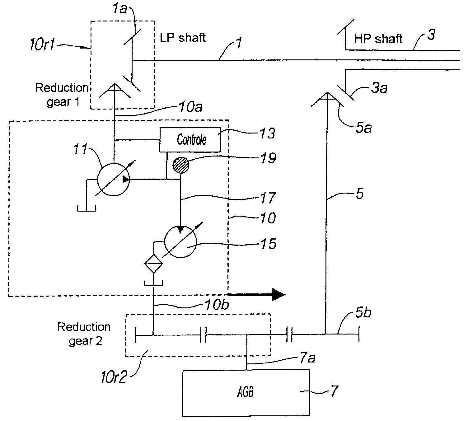
[0034]According to the invention, in this first embodiment, the input shaft 7a is driven by a hydraulic transmission means 10, which is a hydrostatic variator, from the LP shaft. The means 10 is mechanically connected via a second mechanical transmission 10r1 to the shaft 1. It may be a pinion meshing on a pinion fixedly attached to the shaft 1. It may also be a speed reduction gear device if that is necessary. The means 10 is mechanically connected via a shaft 10b to the input shaft 7a of the gearbox here by means of a speed reduction gear device, forming a third mechanical transmission 10r2. The hydrostatic transmission comprises a pump 11 driven mechanically by the shaft 10a. The reduction gear 10r1 makes it possible to match the speed of the input shaft to that of the pump. Advantageously it is a positive displacement pump with variable cubic capacity. An example of this type of pump comprises an adjustable inclination plate. The variation of the angle of inclination of the plat...

second embodiment

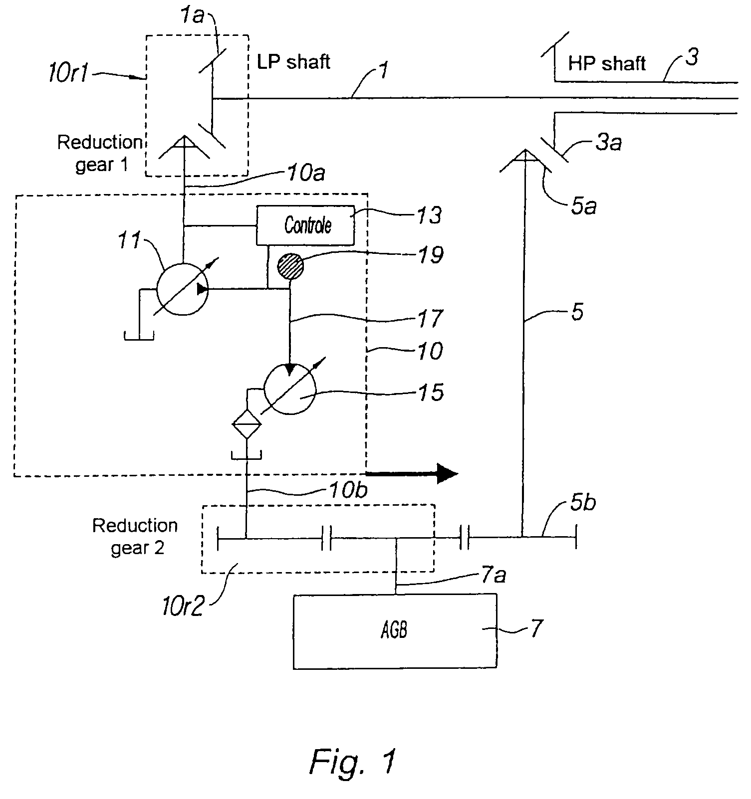
[0044]With reference to FIG. 2, relating to a second embodiment, the elements corresponding to those of FIG. 1 have been shown by adding 200 to the reference numbers. It shows the LP shaft 201 and the HP shaft 203 of the double-shaft turbine engine, not shown. The shaft 203 is connected to the auxiliary machine gearbox 207, the AGB, via a first mechanical transmission 205, here a transmission shaft meshing via a pinion 205a with a pinion 203a of the HP shaft, the two forming an angle transmission.

[0045]According to the invention, a hydraulic transmission is arranged between the LP shaft 201 and the gearbox 207. This transmission forms part of a hydromechanical transmission described hereinafter.

[0046]The hydrostatic part of the transmission comprises, as in the preceding solution, a hydrostatic variator 210. The latter comprises a hydraulic pump 211 and a hydraulic motor 215 connected via a hydraulic circuit 217. The two machines 211 and 217 have variable cubic capacity; this is sho...

third embodiment

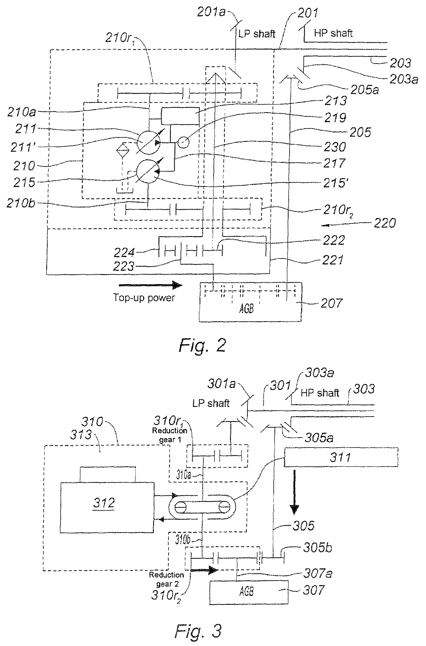
[0060]With reference to FIG. 3, relating to a third embodiment, it shows the elements corresponding to those of FIG. 1, by adding 300 to the reference numbers.

[0061]It shows a first and a second shaft, 301 and 303 respectively. These are the LP and HP shafts respectively of a double-shaft gas turbine engine not shown. These two shafts are provided with appropriate pinions 301a and 303a for the movement offtake. The first allows the movement offtake via the input shaft 310a of a transmission device 310, here hydrokinetic. The second 303a allows the movement offtake via the pinion 305a of a transmission shaft 305 forming the first transmission means. Between the pinion 301a and the input shaft 310a, a second mechanical transmission 310r1 is provided in the form of a speed reduction gear.

[0062]As in the preceding cases, an accessory gearbox 307, offset relative to the motor, is driven by these two means. The first means 310 comprises a shaft 310b driving the shaft 307a via a speed redu...


PUM


Abstract

A device drives auxiliary machines by using power extracted from a multi-shaft gas turbine engine. The gas turbine engine may include a LP shaft and a HP shaft. The machines may be installed in a gearbox. The device may include a first mechanical transmission between the HP shaft and the gearbox. The device also may include a hydraulic transmission between the LP shaft and the gearbox. Further, the LP shaft connects a low pressure turbine to a low pressure compressor, the HP shaft connects a high pressure turbine to a high pressure compressor, and the low pressure compressor is upstream of the high pressure compressor.

Description

BACKGROUND OF THE INVENTION[0001]1. Field of the Invention[0002]The present invention relates to the field of multi-shaft gas turbine engines, for aviation application in particular, and is aimed at a means of offtaking mechanical power from the rotor shafts in order to drive accessories.[0003]2. Description of Related Art[0004]A gas turbine engine usually comprises an air compressor set at least partially supplying a combustion chamber. The gases from the latter drive one or more turbines mechanically connected to the compressors, and supply the thrust. A double-shaft engine comprises a “low pressure” compressor set connected via a first shaft to a group of low pressure turbines, the assembly forming the low pressure, LP, shaft. It also comprises a second shaft, called the high pressure, HP, shaft, fixedly attached to a second shaft concentric with the first. The two rotors are mechanically free to rotate relative to one another. The HP shaft is in direct communication with the com...

Claims


Application Information

Patent Timeline
IPC IPC(8): F16H47/00F02C1/06F16H37/06
CPCF02C3/107F02C7/32F02C7/36F16H47/04Y10T74/19093Y02T50/671Y10T74/19033Y10T74/19037F16H2037/088Y02T50/60
Inventor LINET, HUGUES HENRI RAYMONDMOUCHNINO, CYRIL FRANCKPETTINOTTI, SERGE DOMINIQUE
Owner SAFRAN TRANSMISSION SYST
Learn More