Fastening device for an orthesis or prosthesis
- Summary
- Abstract
- Description
- Claims
- Application Information
AI Technical Summary
Benefits of technology
Problems solved by technology
Method used
Image
Examples
second embodiment
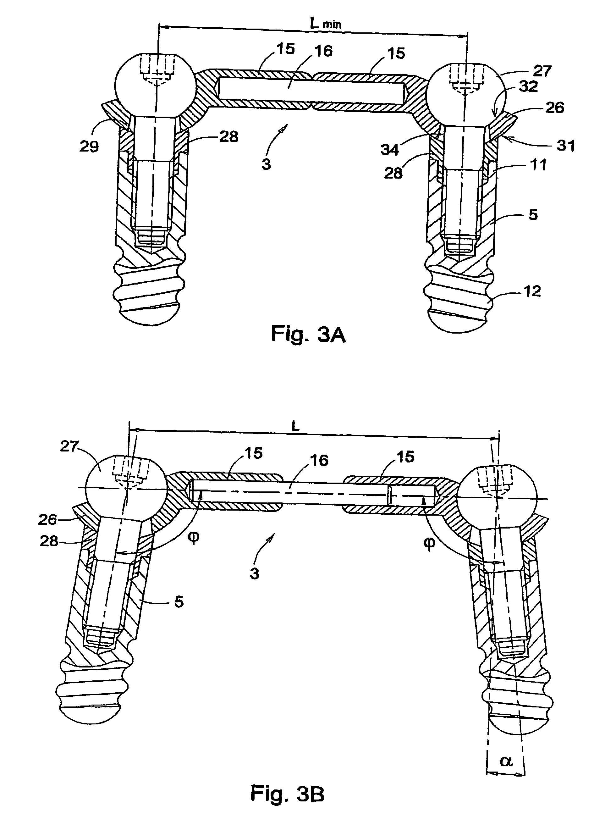
[0033]In FIGS. 3A and 3B, a device 1 according to the invention is shown. The device 1 comprises a bar assembly 3 which is secured on two implants 5, with the aid of coupling elements 28 and fastening screws 27. The bar assembly 3 comprises, as the embodiment shown in FIG. 1, two substantially tubular bar arms 15 which are slideably arranged on two ends of a bar rod 16. The extremities 26 of these bar arms 15 have a ball-shaped side 31 proximal to the implant 5, and a socket-shaped side 32 proximal to the fastening screw 27. Further, each extremity 26 is provided with a conical hole 34, for the passage of the fastening screw 27. The coupling element 28 and the fastening screw 27 together enclose a space in which the extremity 26 of the bar assembly 3 can be pivotally received. To that end, the fastening screw 27 is provided with a ball-shaped head cooperating with the socket-shaped side 32 of the bar arm end 26, and the coupling element 28 has a socket-shape cooperating with the bal...
third embodiment
[0036]In FIGS. 4A and 4B, a device 1 according to the invention is shown, wherein FIG. 4A shows a situation in which the implants 5 are both provided in the bone in a straight manner and FIG. 4B shows a situation in which the implants 5 are at an angle α. Like the previous embodiments, the bar assembly 3 comprises two substantially tubular bar arms 15, slid on opposite sides on a bar rod 16, and with which the length L of the bar assembly 3 can be varied between a minimum and maximum value Lmin, Lmax. Each bar arm 15 is provided with a ring-shaped end 36, provided around a ball-shaped head 37 of a fastening screw 38. Here, the shape and dimension of the ring 36 are such that this cannot be detached from the head 37, but can pivot freely relative to this head 37, so that a desired angle φ between the longitudinal axes of the bar arm 15 and the implant 5 can be set. An advantage of this embodiment is that the angle φ is adjustable over a relatively large range, so that this bar assemb...
fourth embodiment
[0037]FIGS. 5A-5C show the device 1, at least a half thereof, wherein the angle φ between the longitudinal axes of the bar arm 15 and an implant 5 can be set with the aid of a cylindrical coupling element 40, divided in two halves 40A, 40B along a diagonal separation surface 41. The bar arm 15 is provided with a disc-shaped end 42, which is secured on the implant 5 between the two halves 40A, B of the coupling element 40 with the aid of a fastening screw 43. For the passage of this fastening screw 43, both coupling element halves 40A, B are provided with a through hole 44 and the end 42 of the bar arm 15 is provided with a tapering hole 45, the smallest diameter of which is equal to the diameter of the hole 44 in the coupling element halves 40A, B. The angle φ between the bar arm 15 and the implant 5 can be varied by rotating both halves 40A, B simultaneously about their longitudinal axis. This is illustrated in FIGS. 5A-5C. FIG. 5A shows a first extreme position in which the bar ar...
PUM
 Abstract
Description
Claims
Application Information
 - R&D
- Intellectual Property
- Life Sciences
- Materials
- Tech Scout
- Unparalleled Data Quality
- Higher Quality Content
- 60% Fewer Hallucinations
Browse by: Latest US Patents, China's latest patents, Technical Efficacy Thesaurus, Application Domain, Technology Topic, Popular Technical Reports.
© 2025 PatSnap. All rights reserved.Legal|Privacy policy|Modern Slavery Act Transparency Statement|Sitemap|About US| Contact US: help@patsnap.com


