
Coupling plate for a fifth wheel coupling

Active Publication Date: 2020-02-06
JOST WERKE DEUT GMBH
View PDF0 Cites 0 Cited by
  • Summary
  • Abstract
  • Description
  • Claims
  • Application Information

AI Technical Summary

Benefits of technology

The patent text describes a way of strengthening a coupling plate on a semitrailer by adding stiffening elements to it. These elements can be mounted on the coupling plate using connection means. A stiffening element can provide increased bending stiffness, but it also adds weight to the coupling plate. To address this, an elastic damping element can be included between the stiffening element and the bearing location to slow down the build-up of force and make the installation and removal of the stiffening element easier. This solution helps to increase the strength of the coupling plate without adding too much weight to it.

Problems solved by technology

However, with the mounting of the at least one stiffening element on the coupling plate the natural weight of the coupling plate is also increased by the weight of the at least one stiffening element.

Method used


Image

  • Coupling plate for a fifth wheel coupling
  • Coupling plate for a fifth wheel coupling
  • Coupling plate for a fifth wheel coupling

Examples


first embodiment

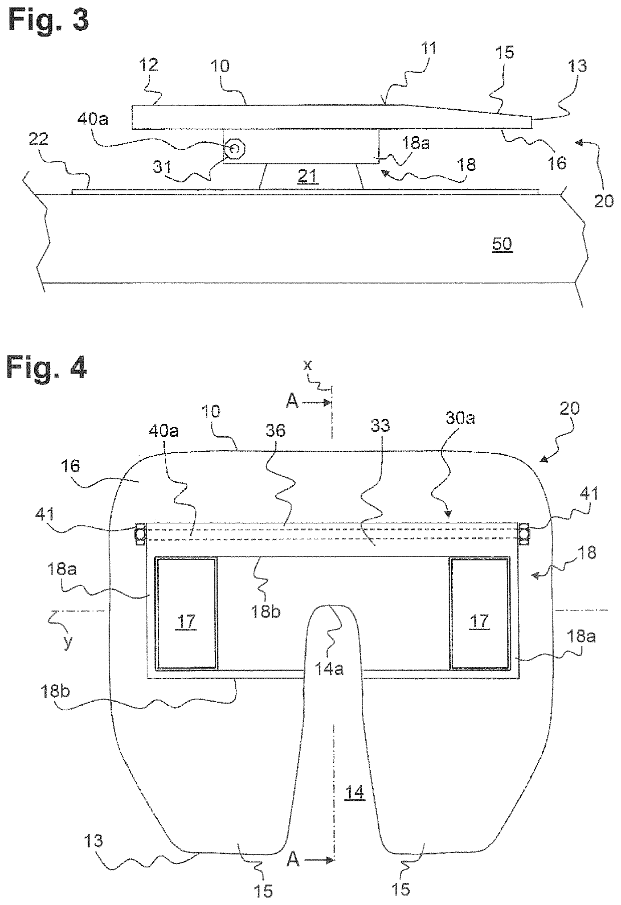
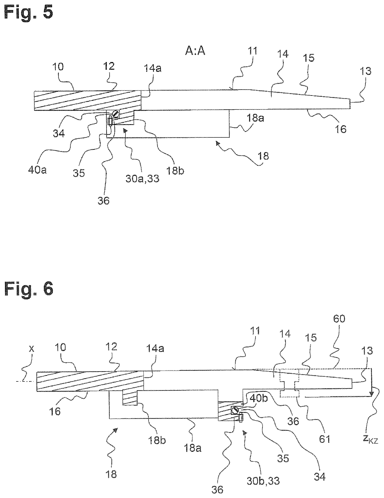
[0052]In the installed position, the horizontal wall extension 36 engages behind the first stiffening element 40a extending between the outer bearing locations 31 from below. If one side of the coupling plate 10 is lifted up, the first stiffening element 40a also begins to deform plastically on account of the bending strain of the coupling plate 10 in the transverse axis y until it comes to bear against the horizontal wall extension 36 of the transverse rib 18b. The formation of the horizontal wall extension 36 on the transverse rib 18b and a resulting central bearing opening 34 to receive the first stiffening element 40a is especially evident in the longitudinal section view of FIG. 5. The central bearing opening 34 is aligned with the outer bearing openings 32 on both sides.

second embodiment

[0053]FIG. 4 and FIG. 5 show the invention, in which the outer bearing locations 31 have been omitted and the first stiffening element 40a is held solely by the central bearing location 33. The central bearing location 33 for this purpose extends in the direction of the transverse axis y approximately over the entire width of the transverse rib 18b, which for this purpose likewise has a horizontal wall extension 36, per FIG. 5, against which the first stiffening element 40a lies.

[0054]Due to the lack of outer bearing locations 31, which bring about a fixation of the first stiffening element 40a in its radial direction by means of their outer bearing openings 32 which are closed in the circumferential direction, the first stiffening element 40a here is protected by closure means 35 against loss in the radial direction. The closure means 35 ensures a narrowing of the central bearing opening 34, so that the first stiffening element 40a can no longer pass in the radial direction through...


PUM


Abstract

A coupling plate for a fifth wheel coupling, wherein the coupling plate on a top side includes a planar bearing surface and at a rear end it includes two entrance horns bordering on an entrance opening, the entrance opening extends in a longitudinal axis (x) of the coupling plate and ends in a kingpin bearing region, and the coupling plate is configured with a respective receiving structure for a bearing block on its bottom side, on either side of the kingpin bearing region and spaced apart from each other on a transverse axis (y). The problem which the invention proposes to solve is to provide a standardized coupling plate, having a minimal natural weight, given a slight loading, and whose strength can be adapted for higher anticipated loads. The problem is solved according to the invention in that at least one connection means for the releasable mounting of at least one stiffening element is formed on the coupling plate beneath the planar bearing surface.

Description

FIELD OF THE INVENTION[0001]The invention relates to a coupling plate for a fifth wheel coupling, wherein the coupling plate on a top side comprises a planar bearing surface and at a rear end it comprises two entrance horns bordering on an entrance opening, the entrance opening extends in a longitudinal axis (x) of the coupling plate and ends in a kingpin bearing region, and the coupling plate is configured with a respective receiving structure for a bearing block on its bottom side, on either side of the kingpin bearing region and spaced apart from each other on a transverse axis (y). Furthermore, the invention is also protected in combination with a stiffening element.BACKGROUND OF THE INVENTION[0002]By means of a fifth wheel coupling, a semitrailer is usually coupled releasably to a tractor vehicle. The fifth wheel coupling for this purpose is secured on the tractor vehicle and comprises, besides a coupling plate, also a closure mechanism, by means of which a kingpin arranged in ...

Claims


Application Information

Patent Timeline
IPC IPC(8): B60D1/01B60D1/36
CPCB60D1/015B60D1/36B62D53/08B62D53/0807
Inventor POLTE, JENSALGÜERA, JOSÉ MANUEL
Owner JOST WERKE DEUT GMBH
Learn More