
Protection and control system for electric power networks with signal and command interfaces at the primary equipment

a technology of electric power network and signal and command interface, which is applied in non-electric variable control, process and machine control, instruments, etc., can solve the problems of copper wiring impact, significant cost associated with building or retrofitting such systems, and the need for miles of copper wiring to interconnect primary equipment, etc., to reduce or eliminate the external time synchronization of master and slave devices, reduce the cost of building, and eliminate the effect of external time synchronization

Active Publication Date: 2010-04-06
GENERAL ELECTRIC CO
View PDF10 Cites 48 Cited by
  • Summary
  • Abstract
  • Description
  • Claims
  • Application Information

AI Technical Summary

Benefits of technology

The technology described in this patent provides a new power substation architecture that overcomes the disadvantages of conventional methods. It reduces the need for millions of copper wire terminations, simplifies the process of building or retrofitting a power substation, and eliminates the need for extra devices to relay control data. The architecture also allows for internal, on-the-fly time synchronization for one or more pieces of primary equipment. The new substation architecture includes a brick that interfaces with the primary equipment and converts analog signals to digital representations, and can execute commands. The system also includes a patch panel and intelligent electronic devices for routing and synchronizing data. The technical effects of this technology include reducing costs, simplifying the process, and improving synchronization.

Problems solved by technology

A disadvantage of separating conventional IEDs from their managed pieces of primary equipment is that miles of copper wiring are needed to interconnect the primary equipment with the conventional IEDs.
Another disadvantage is the significant cost associated with building or retrofitting such systems, due to the millions of wire terminations involved.
The majority of this cost relates to the design, installation, testing, and documentation of the control wiring.
Preliminary approaches at implementing this standard and reducing the impact of copper wiring, however, fail to provide specific teachings or a solid, workable architecture.
Such approaches, and the standard itself, leave numerous gaps yet to be filled in.

Method used


Image

  • Protection and control system for electric power networks with signal and command interfaces at the primary equipment
  • Protection and control system for electric power networks with signal and command interfaces at the primary equipment
  • Protection and control system for electric power networks with signal and command interfaces at the primary equipment

Examples


Embodiment Construction

[0025]Reference is made herein to the accompanying drawings briefly described above, which show by way of illustration various embodiments of the claimed invention. Persons of ordinary skill in the above-referenced technological field will recognize that other embodiments may be utilized, and that structural, electrical, and procedural changes may be made without departing from the scope of the claimed invention. As used herein, the singular (illustratively, “brick”) includes the plural (illustratively, “bricks”), and the plural includes the singular.

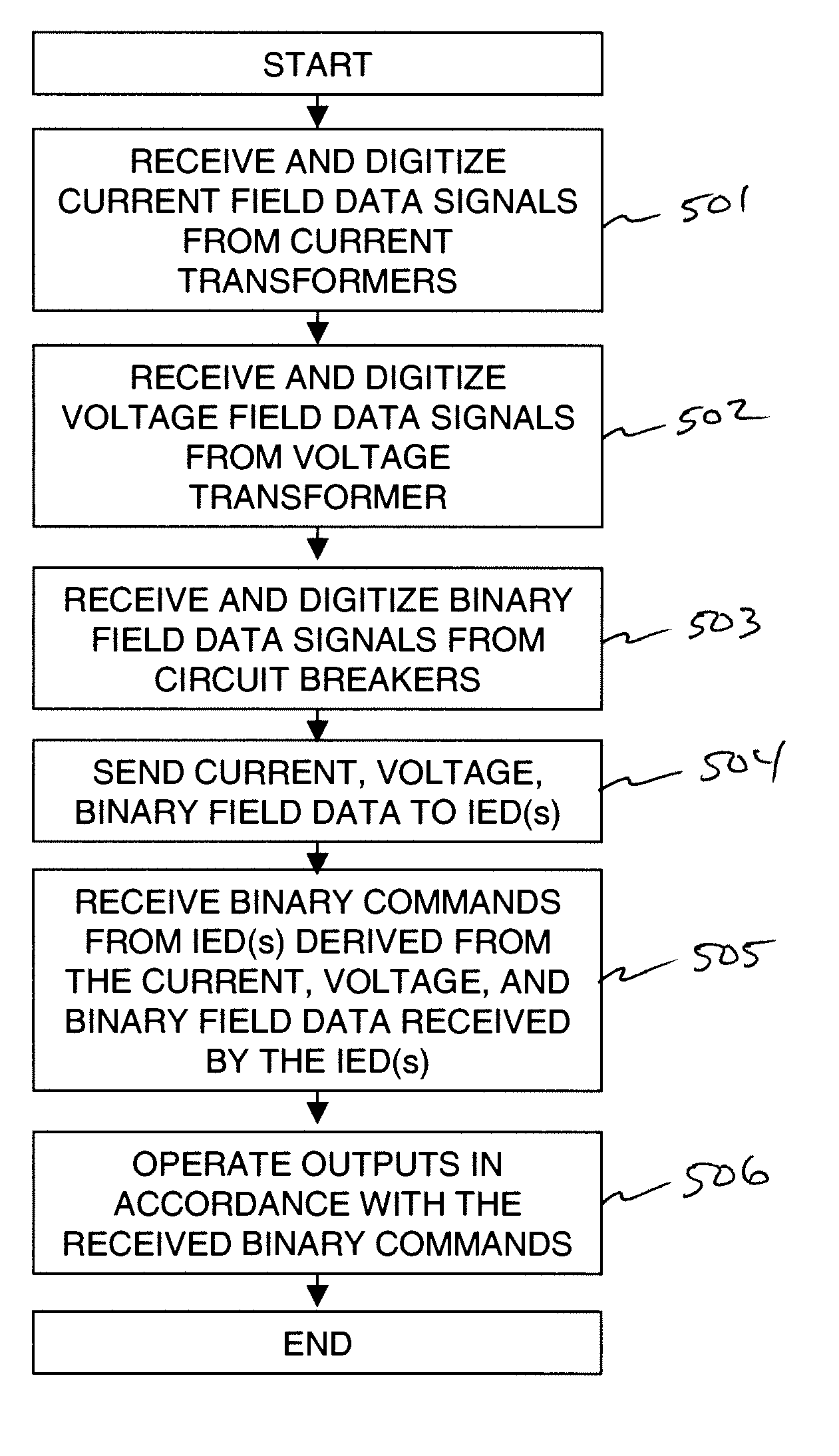
[0026]FIG. 1 is a schematic diagram of a power substation architecture 100 configured according to an embodiment of the invention. Referring to FIG. 1, two fiber-optic patch panels 130 and 140 are disposed between a switchyard 150 and a relay control house 160. The switchyard 150 comprises one or more pieces of primary equipment, such as, but not limited to, the high voltage apparatus 102. Each piece of primary equipment may be directly...


PUM


Abstract

A system for protection, control, metering, and monitoring of the delivery of electrical power is disclosed. Embodiments of the system provide input / output devices called bricks to receive analog and binary field data from primary equipment located in a power substation switchyard. The bricks are linked via fiber-optic patch cables and patch panels with one or more intelligent electronic devices (“IEDs”). In operation, the bricks convert the received binary and / or analog field data into digital signals, and transmit the digital signals synchronously to their associated IEDs using clock signals provided by each IED to the individual bricks. The bricks may accept a computer software code download from each of its master IED(s). Multiple code implementations, each tailored to the requirements of its master IED(s) can therefore co-exist on a single brick.

Description

BACKGROUND[0001]1. Field of the Invention[0002]The field of the invention generally relates to the commercial and industrial production of electrical power and, more particularly, to a system and method for protecting and controlling electric power networks.[0003]2. Description of Related Art[0004]A typical power distribution grid generally includes a power plant, a transmission substation, high voltage transmission lines, and a power substation. The power plant's spinning generator outputs three-phase alternating-current (AC) electrical power, which leaves the generator and enters the transmission substations. Transformers at the transmission substation substantially boost the generator voltage to a high voltage sufficient to transmit the electrical power over long distances via the high voltage transmission lines. Before the transmitted electrical power is used by homes or industry, it passes through a power substation.[0005]A power substation generally includes transformers that ...

Claims


Application Information

Patent Timeline
Patent Type & Authority Patents(United States)
IPC IPC(8): H02J13/00
CPCH02J13/0065Y02E60/723Y02E60/724Y02E60/74Y04S10/18Y04S10/30Y04S10/16H02H3/05H02J13/00019H02J13/00002H02J13/00017H02J13/00034H02J13/0004Y02E60/00Y04S40/124Y02B90/20H02J13/00Y04S10/20
Inventor KASZTENNY, BOGDAN Z.FINNEY, DALEMAZEREEUW, JEFFREYMARUSCA, IOAN
Owner GENERAL ELECTRIC CO
Learn More