Latency measurement apparatus and method
a technology of latency measurement and measurement apparatus, applied in the field of latency measurement apparatus and method, can solve the problems of high cost associated with developing, purchasing, selling and deploying a new wireless technology, notoriously difficult testing of wireless devices, and inability to meet the needs of wireless devices, etc., to achieve enhanced roaming testing capabilities, easy to change the configuration of the test network, and increase the effect of signal attenuation
- Summary
- Abstract
- Description
- Claims
- Application Information
AI Technical Summary
Benefits of technology
Problems solved by technology
Method used
Image
Examples
embodiment 195
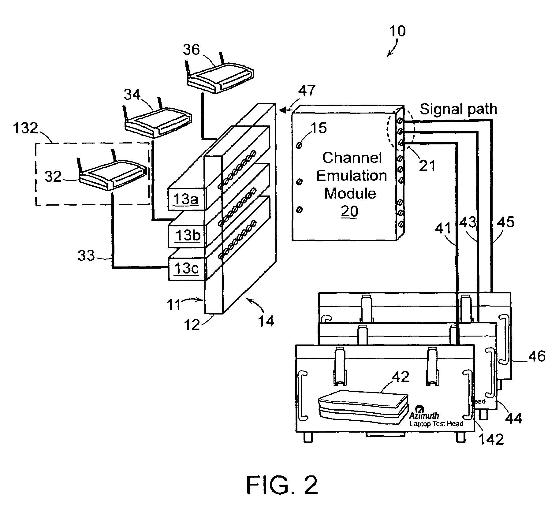
[0062]Referring now to FIG. 10, an illustration a first analog embodiment 195 of the channel emulator component is shown. The channel emulator 195 adds channel effects to the bidirectional signals exchanged between the backplane and the RF ports 21 of the channel emulator module. For purposes only of facilitating understanding of the below description, the term ‘forward’ path shall be used to describe transmissions on a path originating at the backplane and ending at the RF Ports 21, and the term ‘reverse path’ will be used to describe transmissions on a path originating at the RF Ports 21 and directed at the backplane. The illustrated embodiment shows circuitry that may be included to add multipath to each one of N paths included in an N×M multipath transmission channel under test. The RF channel emulator 195 includes a splitter / combiner 73 coupled to a plurality of delay lines 75 and a plurality of programmable attenuators 76. The delay lines are coupled to a splitter / combiner 77....
embodiment 495
[0067]Referring now to FIG. 13, an embodiment 495 of an RF channel emulator is shown wherein the reverse path circuitry is similar to the forward path circuitry described in FIG. 12. Thus in the reverse path a second RF to IF down converter 244 is provided for converting received RF signals from circulator 222 to the mixer that down-converts the RF signal to IF, a DSP engine 242, an IF to RF up-converter 240 and programmable attenuation 245. DSP engine 242 and attenuation 245 are independently programmable and thereby allow different characteristics to be modeled on the return path.
[0068]One example of how the MIMO channel emulation modules may be used in a test environment is shown in FIG. 14. In FIG. 14 the test bed includes two MIMO channel emulation modules 94 and 96. MIMO access point DUT antenna ports are coupled to the RF ports of each of the modules 94, and 96, and a MIMO client DUT 78 is coupled to RF combiners 13a-13c. A variety of channel effects, including multipath, pat...
PUM
 Abstract
Description
Claims
Application Information
 - R&D
- Intellectual Property
- Life Sciences
- Materials
- Tech Scout
- Unparalleled Data Quality
- Higher Quality Content
- 60% Fewer Hallucinations
Browse by: Latest US Patents, China's latest patents, Technical Efficacy Thesaurus, Application Domain, Technology Topic, Popular Technical Reports.
© 2025 PatSnap. All rights reserved.Legal|Privacy policy|Modern Slavery Act Transparency Statement|Sitemap|About US| Contact US: help@patsnap.com


