
Sheet width control for overflow downdraw sheet glass forming apparatus

a technology of forming apparatus and sheet width control, which is applied in the field of glass sheet manufacturing, can solve the problems of uneven sheet thickness distribution, adverse effect of increased shortening on the width of manufactured sheet, and inability to maintain the optimum shape of forming block, so as to minimize the distortion of forming block trough and weir

Inactive Publication Date: 2010-04-06
CORNING INC
View PDF68 Cites 10 Cited by
  • Summary
  • Abstract
  • Description
  • Claims
  • Application Information

AI Technical Summary

Benefits of technology

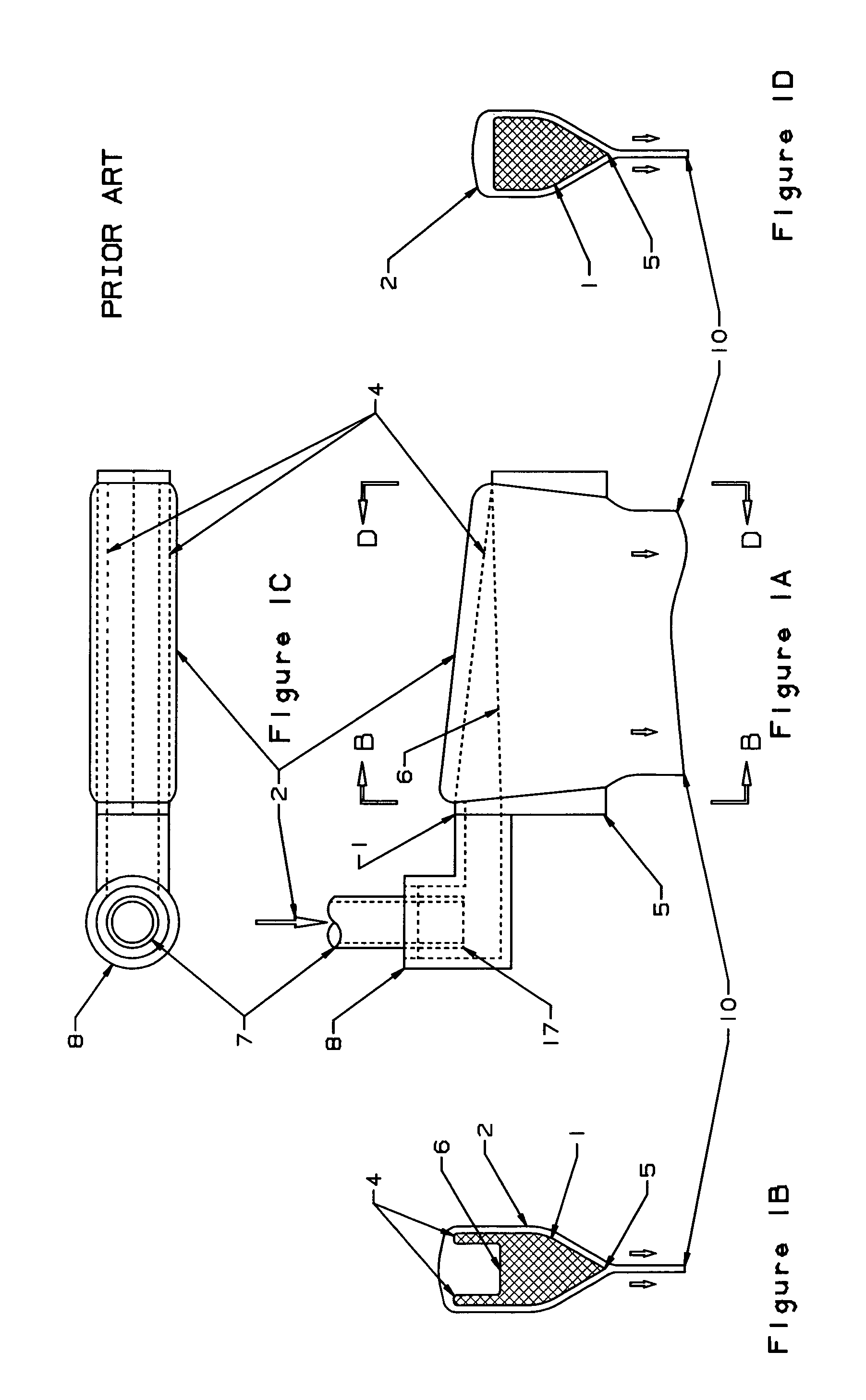
The present invention is a significant modification of a glass manufacturing process called "The Overflow Process." The invention introduces several new features that improve the manufacturing process. First, the invention allows for better control over the width of the manufactured glass sheet by attaching edge directors to the manufacturing apparatus structure instead of the forming block. This results in a longer period of time during which the sheet glass can be manufactured with the same forming block. Second, the invention introduces the use of molybdenum as a material for the forming block, which is less prone to thermal creep than refractory zircon. This results in a longer life for the forming block. Third, the invention introduces the ability to adjust the width of the manufactured sheet by changing the distance between the edge directors. This allows for different width specifications to be manufactured with the same forming block. Fourth, the invention introduces a method to further minimize distortion of the forming block trough and weirs when the forming block changes shape under the influence of thermal creep. Overall, these features improve the efficiency and quality of the glass manufacturing process.

Problems solved by technology

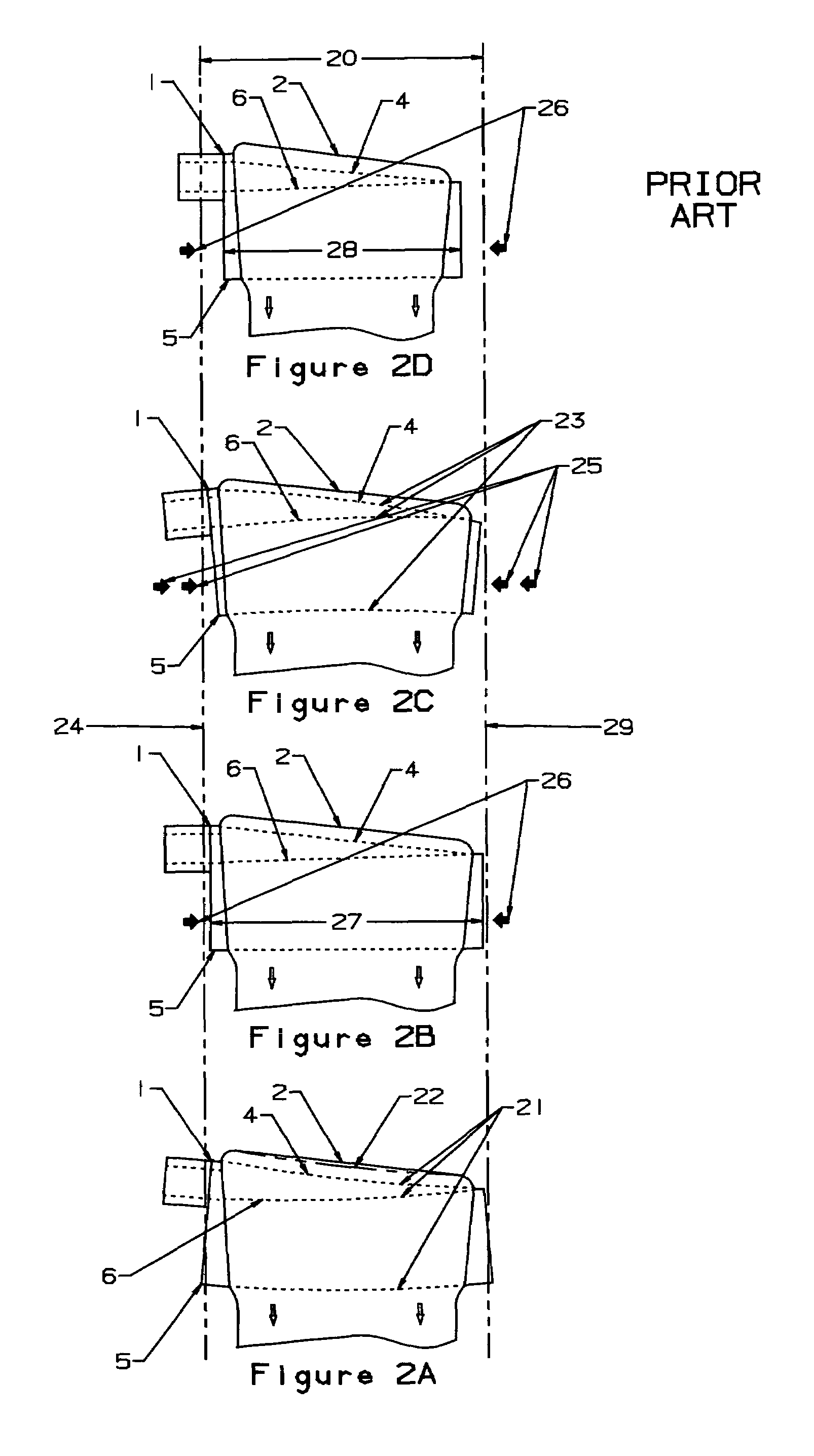
More specifically, the curvature (21) allows more glass to flow over the middle of the weirs resulting in an uneven sheet thickness distribution.
This increased shortening has an adverse effect on the width of the manufactured sheet.
The application of the optimum compression loading (26) minimizes the sagging of the forming block (1), but it does not maintain an optimum shape of the forming block.
This results in less square feet of production and required process adjustments.
A major drawback of the apparatus of “The Overflow Process” is that the forming apparatus deforms during the manufacturing campaign in a manner such that the glass sheet no longer meets the width specification.
This is a cause for premature termination of the production run.
Another major drawback of the apparatus of “The Overflow Process” is that there is no means for adjusting the width of the sheet which is manufactured.
Another major drawback is that although the compression loading of the bottom ends of the forming block corrects for the major portion of the forming block sag caused by thermal creep, this compression loading does introduce a measure of distortion of the forming block weirs and trough bottom.

Method used


Image

  • Sheet width control for overflow downdraw sheet glass forming apparatus
  • Sheet width control for overflow downdraw sheet glass forming apparatus
  • Sheet width control for overflow downdraw sheet glass forming apparatus

Examples


Embodiment Construction

[0161]The present invention is a significant modification of “The Overflow Process” that embodies design features that provide for control over the width of the manufactured glass sheet and improved control of the sheet thickness distribution.

[0162]The terms used herein have many synonymous names. A key component, the “forming block” (5) herein, is also known in the present inventor's other patent applications as a “forming apparatus”, “forming apparatus body”, “wedge shaped forming device”, “sheet forming trough”, “overflow trough”, “forming wedge”, “forming trough”, and “trough”. U.S. Pat. No. 3,338,696 uses the terms “forming device”, “wedge-shaped body portion”, and “cuneiform body portion”. U.S. Pat. No. 3,451,798 uses the term “forming wedge” and U.S. Pat. No. 3,519,411 uses the term “forming member”. A typical term in patent applications assigned to Corning, Inc. is “isopipe”. The “inflow pipe” (8) herein has been called the “inlet pipe” by this inventor in previous patent ap...


PUM

PropertyMeasurementUnit
temperaturesaaaaaaaaaa
glass viscosityaaaaaaaaaa

Abstract

A method keeps the width of the manufactured sheet substantially the same by attaching edge directors for the formed sheet to the manufacturing apparatus structure instead of to the forming block. Thus, sheet glass may be manufactured to specification for a longer time with the same forming block. An additional method adjusts the width of the manufactured sheet by changing the distance between the edge directors. Thus sheet glass may be manufactured to different width specifications with the same forming block.

Description

REFERENCE TO RELATED APPLICATIONS[0001]This application claims an invention, which was disclosed in the following Provisional Applications:[0002]1) Provisional Application No. 60 / 546,875, filed Feb. 23, 2004, entitled “SHEET GLASS FORMING APPARATUS”;[0003]2) Provisional Application No. 60 / 576,274, filed Jun. 2, 2004, entitled “SHEET GLASS FORMING APPARATUS”;[0004]3) Provisional Application No. 60 / 599,620, filed Aug. 6, 2004, entitled “OVERFLOW DOWNDRAW SHEET GLASS FORMING METHOD AND APPARATUS”; and[0005]4) Provisional Application No. 60 / 623,783, filed Oct. 29, 2004, entitled “OVERFLOW DOWNDRAW SHEET GLASS FORMING METHOD AND APPARATUS”.[0006]The benefit under 35 USC §119(e) of the United States provisional applications is hereby claimed, and the aforementioned applications are hereby incorporated herein by reference.BACKGROUND OF THE INVENTION[0007]1. Field of the Invention[0008]This invention relates generally to the manufacture of glass sheet and, more particularly, to glass sheet ...

Claims


Application Information

Patent Timeline
Patent Type & Authority Patents(United States)
IPC IPC(8): C03B17/00C03B17/06
CPCC03B17/064
Inventor PITBLADDO, RICHARD BRUCE
Owner CORNING INC
Learn More