Colorimetry method, colorimetry device, spectral measurement method, spectral measurement device and electronic apparatus
a colorimetry and spectral measurement technology, applied in the direction of optical radiation measurement, instruments, television systems, etc., can solve the problems of excessively high saturation and low brightness of imaging data, and achieve the effect of maintaining the width of brightness, shortening the time for colorimetry, and reducing the number of colors
- Summary
- Abstract
- Description
- Claims
- Application Information
AI Technical Summary
Benefits of technology
Problems solved by technology
Method used
Image


Examples
first embodiment
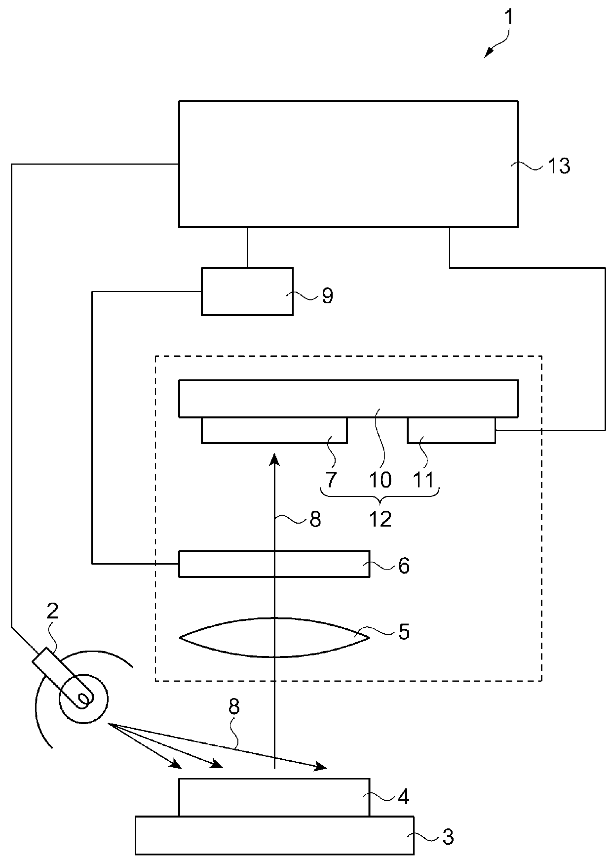
[0058]The colorimetry device and the colorimetry method according to the first embodiment are described with reference to FIGS. 1 to 11. FIG. 1 is a block diagram showing a configuration of the colorimetry device. The colorimetry device 1 includes a light source 2, as shown in FIG. 1. The light source 2 radiates a reference light such as white light. The light source 2 is constructed by combining an incandescent lamp and a light filter. In addition, adjustment may be performed so that the light radiated has a predetermined wavelength distribution by combining a plurality of colors of light emitting diodes (LED).
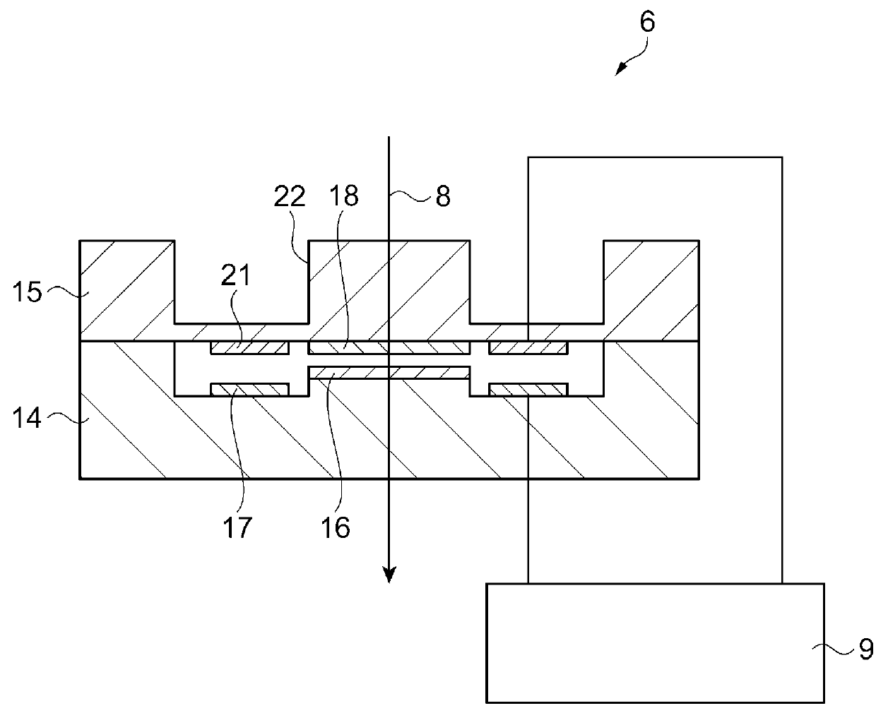
[0059]A mounting stand 3 is arranged at a location facing the light source 2 and a measurement object 4 is mounted on the mounting stand 3. An imaging lens 5 is arranged at a location facing the measurement object 4. A light filter 6 and a light receiving element array 7 are arranged lined up in this order on the optical axis of the imaging lens 5. Light 8 radiated from the l...
second embodiment
[0113]Next, an embodiment of the colorimetry method is described using drawings for describing the colorimetry method of FIG. 12. The embodiment differs from the first embodiment on the feature that the operator performs setting of the exposure time shown in FIG. 11. The same features as the first embodiment will not be described.
[0114]FIG. 12 is a drawing corresponding to the brightness determination process in the step S5. The vertical and horizontal axes in FIG. 12 are the same as FIG. 11, and description thereof will not be made. That is, in the embodiment, in the first imaging, the exposure time is a short time, and in the second imaging, re-imaging is performed while changing the exposure time to a long exposure time. The third to sixth imagings are normal imagings. At this time, the operator sets the exposure time while checking the measurement object 4. In the seventh imaging, re-imaging is performed while changing the exposure time to a long exposure time. The eighth and ni...
third embodiment
[0117]Next, an embodiment of the colorimetry method is described using drawings for describing the colorimetry method of FIGS. 13 to 15. The embodiment differs from the first embodiment on the feature of performing determination of re-imaging for each row of output of the imaging device 12. Also, the light receiving element array 7 is changed from a CCD image sensor to a CMOS image sensor. In so doing, the light receiving element array 7 is able to output the imaging data for each row. The same features as the first embodiment will not be described.
[0118]FIG. 13A shows an image 75 imaged by the imaging device 12. A first region 75a is a bright region, and a second region 75b is a dark region. The image 75 is two-dimensional data having a plurality of rows. The horizontal direction in the drawing is the X direction. The X direction is the horizontal scanning direction. The vertical direction is the Y direction. The Y direction is the vertical scanning direction. One scanning line for...
PUM
 Abstract
Description
Claims
Application Information
 - R&D
- Intellectual Property
- Life Sciences
- Materials
- Tech Scout
- Unparalleled Data Quality
- Higher Quality Content
- 60% Fewer Hallucinations
Browse by: Latest US Patents, China's latest patents, Technical Efficacy Thesaurus, Application Domain, Technology Topic, Popular Technical Reports.
© 2025 PatSnap. All rights reserved.Legal|Privacy policy|Modern Slavery Act Transparency Statement|Sitemap|About US| Contact US: help@patsnap.com