
Register retiming technique

a register retiming and register technology, applied in the field of electronic design automation of logic design, can solve the problems of increasing complexity of programmable logic integrated circuits such as pals, plds, fpgas, and increasing difficulty in ensuring the implementation of logic functions in an optimal way, and achieve the effect of improving the maximum operating frequency or fmax

Inactive Publication Date: 2010-03-30
ALTERA CORP
View PDF5 Cites 28 Cited by
  • Summary
  • Abstract
  • Description
  • Claims
  • Application Information

AI Technical Summary

Benefits of technology

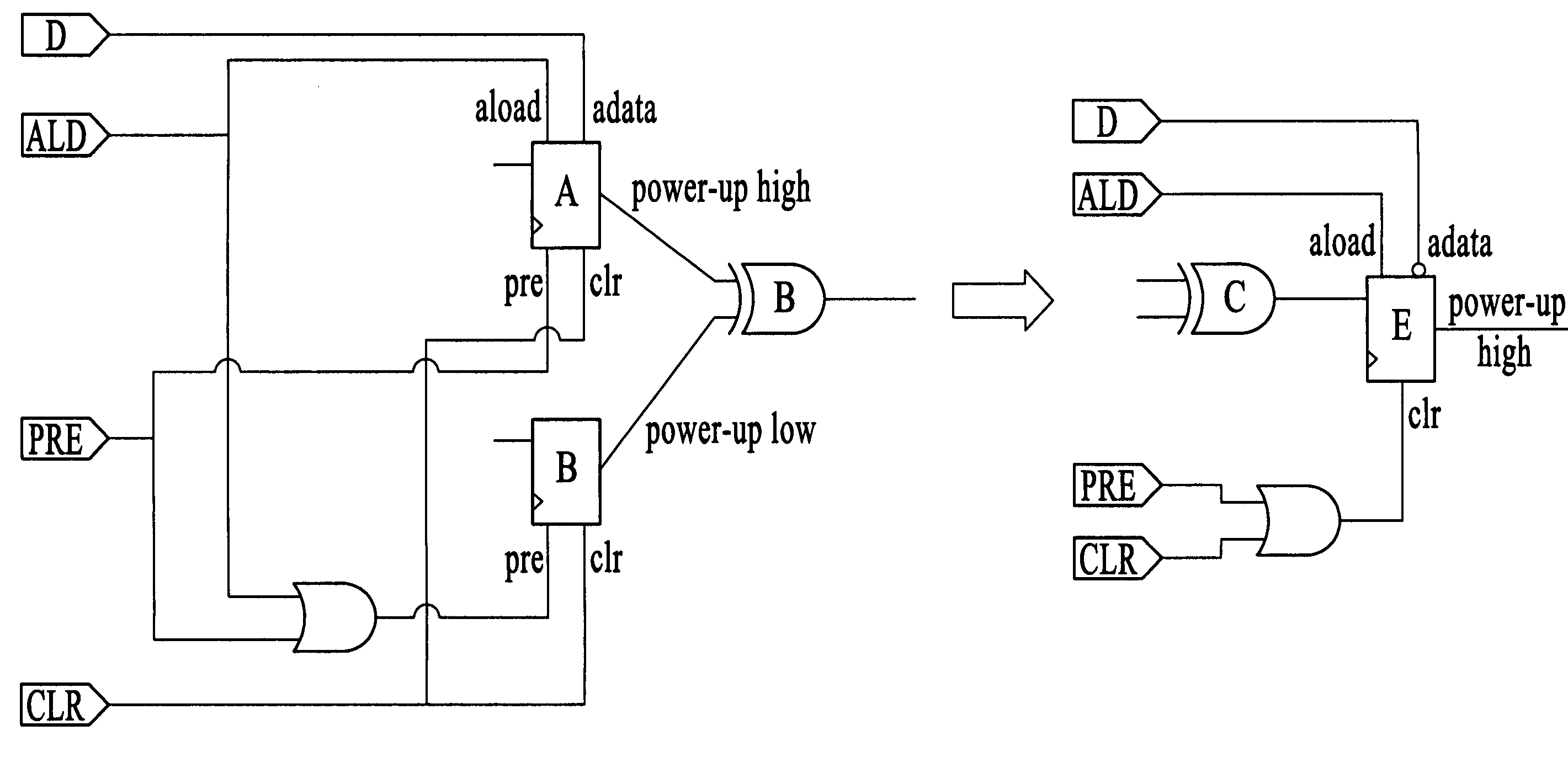
The present invention is a computer-aided design system and method for improving the performance of integrated circuits by automatically optimizing the placement and routing of registers in a logic design. The invention uses a technique called register retiming to improve the maximum operating frequency (fmax) of the circuit. The invention is efficient and can avoid certain issues that other algorithms may cause. It can also be applied to different types of logic circuits such as programmable logic devices. The invention allows for the movement of registers across combinational logic and can balance the lengths of longer paths and asynchronous paths. The method includes finding design conditions and disallowing the movement of registers when performing register retiming. Overall, the invention improves the performance of logic circuits by optimizing register placement and routing.

Problems solved by technology

Programmable logic integrated circuits such as PALs, PLDs, FPGAs, LCAs, and others are becoming more complex and continually evolving to provide more user-programmable features on a single integrated circuit.
As integrated circuits become more complex and provide more functionality in a smaller die size, it also becomes increasingly difficult to ensure the logic functions are implemented properly and in an optimal way.
But even with the help of computer-aided tools, the process of optimizing an integrated circuit design can be time-consuming because of the large number of variables involved.
It is important to be careful when implementing retiming because retiming can be a relatively dangerous operation in a synthesis flow due to its effects on simulation, verification and debug, and other issues such as metastability, and because a timing visibility early in a CAD flow is typically significantly less than desired.

Method used


Image

  • Register retiming technique
  • Register retiming technique
  • Register retiming technique

Examples


Embodiment Construction

Computer Aided Design System with Retiming

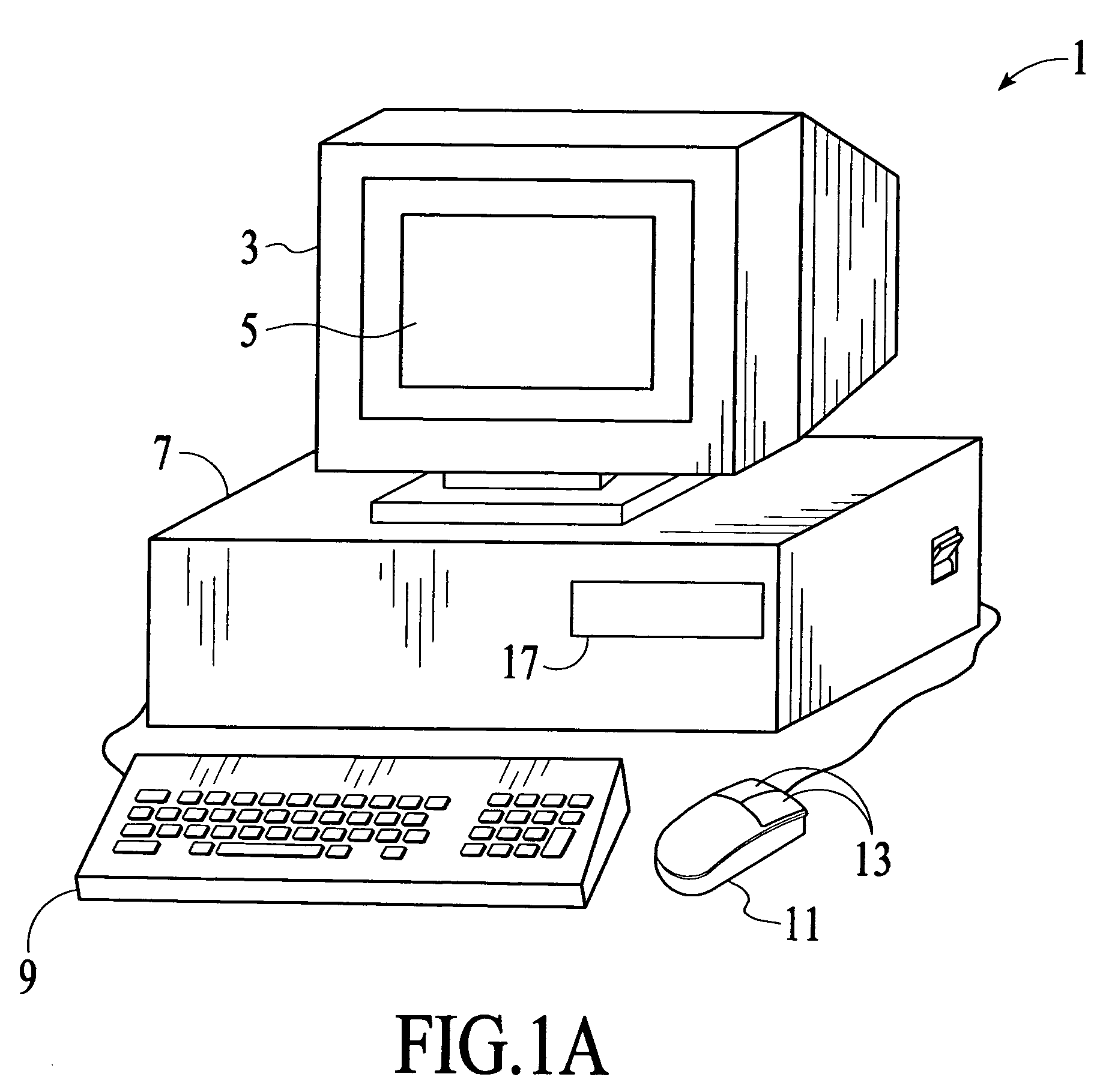
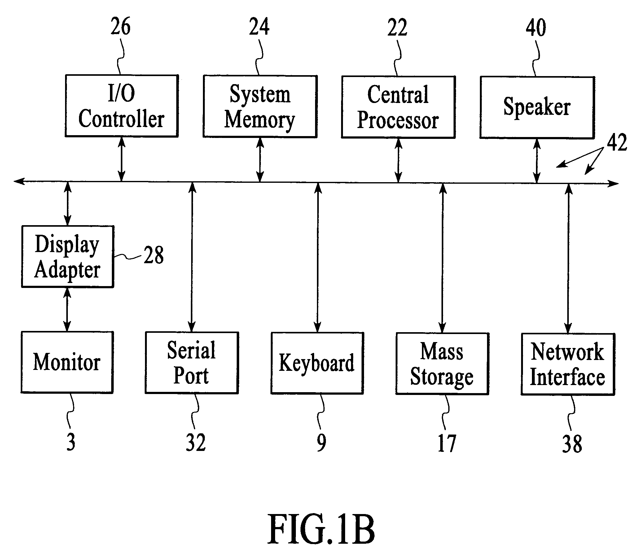
[0042]FIG. 1A shows a system of the present invention for performing register retiming. In an embodiment, software of the invention executes on a computer workstation system, such as shown in FIG. 1A. FIG. 1A shows a computer system 1 that includes a monitor 3, screen 5, cabinet 7, keyboard 9, and mouse 11. Mouse 11 may have one or more buttons such as mouse buttons 13. Cabinet 07 houses familiar computer components, some of which are not shown, such as a processor, memory, mass storage devices 17, and the like. Mass storage devices 17 may include mass disk drives, floppy disks, Iomega ZIP™ disks, magnetic disks, fixed disks, hard disks, CD-ROMs, recordable CDs, DVDs, DVD-R, DVD-RW, Flash and other nonvolatile solid-state storage, tape storage, reader, and other similar media, and combinations of these. A binary, machine-executable version, of the software of the present invention may be stored or reside on mass storage devices 17. Furthermo...


PUM


Abstract

An electronic automation system performs register retiming on a logic design, which may be a logic design for a programmable logic integrated circuit. Register retiming is a moving or rearranging of registers across combinatorial logic in a design in order to improve a maximum operating frequency or fmax. In one implementation, the system includes machine-readable code, which may be stored on a computer-readable medium such as a disk, executing on a computer. The system balances timing in order to trade off delays between critical and noncritical paths. Register retiming may make changes to a design at a gate level.

Description

CROSS-REFERENCE TO RELATED APPLICATIONS[0001]This application is a divisional of U.S. patent application Ser. No. 10 / 446,650, filed on May 27, 2003 entitled “Register Retiming Technique” which is hereby expressly incorporated by reference for all purposes.COPYRIGHT NOTICE[0002]A portion of the disclosure of this patent document contains material which is subject to copyright protection. The copyright owner has no objection to the facsimile reproduction by anyone of the patent document or the patent disclosure, as it appears in the U.S. Patent and Trademark Office patent file or records, but otherwise reserves all copyright rights whatsoever.COMPUTER PROGRAM LISTING APPENDIX[0003]A computer program listing appendix is submitted with this patent document by compact disc (CD-R). There are two compact discs, an original and its duplicate, and all material on the compact discs is incorporated by reference. Each compact disc includes a computer pseudocode listing of an embodiment of the i...

Claims


Application Information

Patent Timeline
Patent Type & Authority Patents(United States)
IPC IPC(8): G06F17/50
CPCG06F17/5045G06F30/30G06F30/34G06F2119/12G06F30/347
Inventor VAN ANTWERPEN, BABETTEHUTTON, MICHAEL D.BAECKLER, GREGGYUAN, RICHARD
Owner ALTERA CORP
Learn More