Fixing device for producing an anchoring in panels, especially panels consisting of glass

a fixing device and glass technology, applied in the direction of screws, threaded fasteners, bolts, etc., can solve the problems of inability to pull out the anchor bolt from the drilled hole, and inability to obtain the undercut suitable for this purpose in the cylindrical drilled hole to any exten

Inactive Publication Date: 2010-03-30
FISCHERWERKE ARTUR FISCHER GMBH & CO KG
View PDF34 Cites 9 Cited by
  • Summary
  • Abstract
  • Description
  • Claims
  • Application Information

AI Technical Summary

Benefits of technology

[0005]The fixing device according to the invention provides an anchoring not by means of expansion but by means of a curable composition, for example an epoxy resin, polyester resin or a mortar. The anchor bolt is surrounded in the region of its anchoring zone with a covering, of a resilient plastics material. This provides the fixing element with resilience in all directions. This also has the effect that the anchor bolt has no contact with the wall of the drilled hole at any point. Without the covering, such contact could occur, for example, as the result of the anchor bolt's being positioned off-centre or hitting the base of the drilled hole while the composition is curing. Whereas such contact can result in the mentioned point loads, a resilient covering ensures distribution over an area.
[0007]The resilience of the fixing device can be controlled, on the one hand, by the thickness and, on the other hand, by the modulus of elasticity of the plastics material used. The wider the covering, the greater the displacements, for example caused by thermal expansions, that can be compensated. Preferably, however, the thickness of the covering is so chosen that the smallest outer diameter of the covering is smaller than the maximum diameter of the anchoring zone of the anchor bolt. As a result, the anchor bolt cannot be pulled out of the drilled hole simply as a result of the covering's shearing off along a cylindrical surface.

Problems solved by technology

It is particularly the case with drilled holes in glass, which are typically drilled with diamond drills, that undercuts suitable for this purpose are not obtained to any extent in cylindrical drilled holes as a result of the very smooth surface.
As a result, the anchor bolt cannot be pulled out of the drilled hole simply as a result of the covering's shearing off along a cylindrical surface.

Method used


Image

  • Fixing device for producing an anchoring in panels, especially panels consisting of glass
  • Fixing device for producing an anchoring in panels, especially panels consisting of glass

Examples


Embodiment Construction

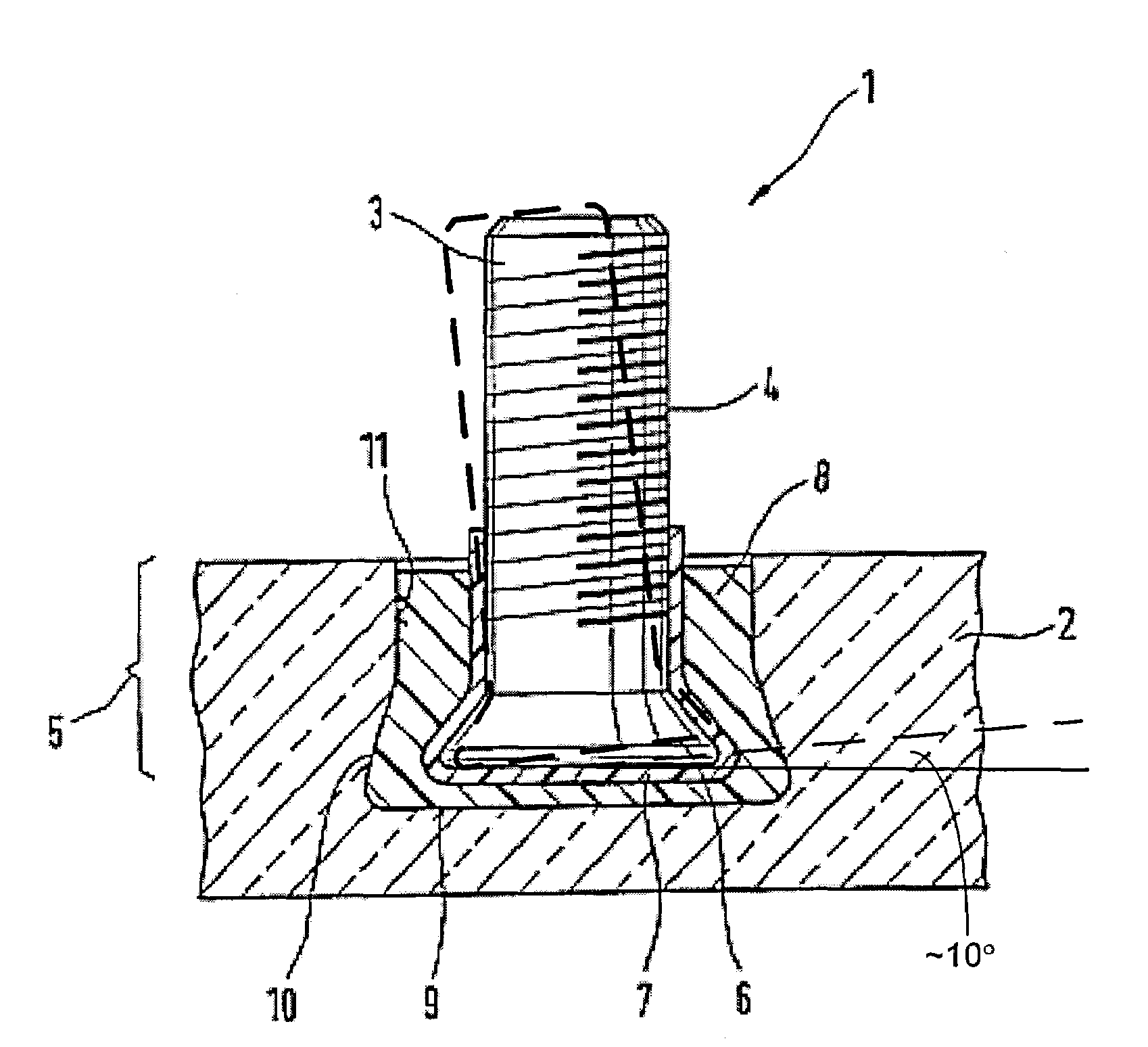
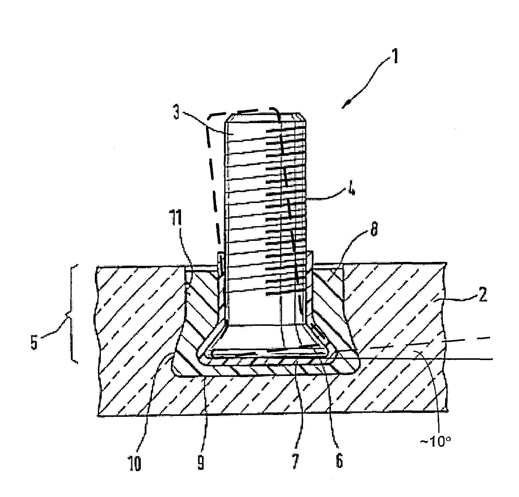
[0010]The invention is described in greater detail below with reference to an exemplary embodiment shown in the drawing. The FIGURE shows a sectional view of a fixing device 1 according to the invention for fixing a glass panel 2. The fixing element has an anchor bolt 3 with an external thread 4 as fixing means and an anchoring zone 5 having a portion 6 that widens conically in cross-section in the direction of insertion. The external thread 4 can be used for attachment to a supporting structure (not shown), for example with the aid of nuts, washers or the like. The anchoring zone 5 has a silicone-containing covering 7 which is surrounded by a cured composition 8. The drilled hole 9 has a conical undercut 10 which prevents the cured composition 8 from being capable of being pulled out of the drilled hole 9 through detachment from the wall 11 of the drilled hole. The thickness of the covering 7 is so chosen that the portion of widened cross-section 6 of the anchoring zone 5 forms an ...


PUM


Abstract

A fixing device is provided for anchoring in an undercut drilled hole in a panel, especially a glass panel, having an anchor bolt. The anchor bolt has fixing means and an anchoring zone having a portion that widens in cross-section in the direction of insertion. In order to provide such a fixing device having increased resilience, the invention proposes that the anchor bolt having a covering of a resilient plastics material in the region of the anchoring zone and that the anchor bolt be anchored by means of a curable composition.

Description

TECHNICAL FIELD OF THE INVENTION[0001]The invention relates to a fixing device for producing an anchoring in panels, especially panels consisting of glass.DESCRIPTION OF THE RELATED ART[0002]The specification DE 43 34 286 C2 discloses a fixing element which is used especially for the fixing of glass panels. It consists of an anchor bolt and an expansion element, the expansion element being anchorable in a drilled hole having an undercut by being drawn into and / or pushed onto the expander cone of the anchor bolt. Between the expansion element and the wall of the undercut drilled hole there is arranged a pressing element of soft plastics material. This has the effect that the holding forces do not give rise to excessive point loads in the drilled hole, such as could not be ruled out in the case of direct contact between metal and glass.[0003]A problem of such anchorings is that they have little flexibility. Particularly during mounting and as a result of thermally induced changes in l...

Claims


Application Information

Patent Timeline
IPC IPC(8): F16B13/00E06B3/54E04F13/08E04F13/14F16B11/00F16B13/14F16B37/04
CPCE04F13/0816E04F13/0835E04F13/145F16B13/141E06B3/5436F16B2013/007F16B11/006F16B37/048E04F13/08E04F13/15F16B13/14
Inventor BOHNET, HARTMUTUNTERWEGER, ROLAND
Owner FISCHERWERKE ARTUR FISCHER GMBH & CO KG
Why Eureka
Try Eureka