Contra rotating generator

a generator and rotating technology, applied in the direction of electric generator control, magnetic circuit rotating parts, magnetic circuit shape/form/construction, etc., can solve the problems of increasing the weight of the tower head, the cost of large rotor blade fabrication at wind farm sites, and the cost of generator physical dimensions, weight, and cost. , to achieve the effect of increasing the relative magnetic flux speed, reducing the physical dimensions of the generator, and reducing the weight of the generator

Inactive Publication Date: 2010-03-16
APPA KARI +1
View PDF15 Cites 25 Cited by
  • Summary
  • Abstract
  • Description
  • Claims
  • Application Information

AI Technical Summary

Benefits of technology

[0006]The contra rotating generator apparatus disclosed herein addresses the above stated need to increase relative magnetic flux speed with reduced generator physical dimensions, weight, and cost.
[0008]Multiple cam followers maintain uniform air gap between the outer surface of the cylindrical armature and the inner surface of the cylindrical magnetic field rotor. The uniform air gap prevents mechanical contact between the cylindrical armature and the cylindrical magnetic field rotor. A sprag clutch prevents unidirectional rotation of the inner shaft and the outer shaft. The contra rotation between the cylindrical armature and the cylindrical magnetic field rotor increases relative magnetic flux speed for generating electrical power at low rotational speeds of the cylindrical magnetic field rotor. The relative magnetic flux speed is the sum of rotational speed of the cylindrical armature and the rotational speed of the cylindrical magnetic field rotor. The contra rotation induces an electric current in the cylindrical armature. Multiple slip rings transport the induced electric current to an external unit. An air gap is maintained at a minimal distance between the cylindrical armature and the cylindrical magnetic field rotor for increasing electromagnetic coupling between the cylindrical armature and the cylindrical magnetic field rotor.
[0009]The cylindrical magnetic field rotor comprises an induction means to produce magnetic flux in the air gap. The induction means comprises one of permanent magnets, magnetic field generating field coils, and a combination thereof. The contra rotating generator further comprises a first laminated yoke for the cylindrical armature and a second laminated yoke for the cylindrical magnetic field rotor. The laminations of the first laminated yoke and the second laminated yoke comprise segmented stampings with an interlocking mechanism and multiple bolt holes. The second laminated cylindrical yoke comprises multiple slots for permanent magnets. The first laminated yoke and the second laminated yoke comprise cylindrical shells of composite materials. The composite materials stiffen the cylindrical shells, minimize aerodynamic drag between the cylindrical armature and the cylindrical magnetic field rotor, and reduce weight of the cylindrical armature and the cylindrical magnetic field rotor.

Problems solved by technology

Moreover, the fabrication of large rotor blades at wind farm sites may not be economical unless a minimum number of rotor blades are built at the same wind farm site.
Furthermore, the rotor blade root-bending moment and the required wall thickness of the rotor blade increases with the square of blade length, resulting in heavier blades that further increase tower head weight.
The generators with large rotor blades may therefore be difficult to transport, install, and maintain in rural or wild terrain environments.
Moreover, due to the heavy weight of the armature, an excess amount of aerodynamic torque may be required to start the rotors rotating, Furthermore, due to small air gap between the armature and the magnetic field unit of the contra rotating wind turbines, the first rotor and the second rotor may come in contact while rotating, thereby resulting in damage of the contra rotating wind turbine.

Method used


Image

  • Contra rotating generator
  • Contra rotating generator
  • Contra rotating generator

Examples


Embodiment Construction

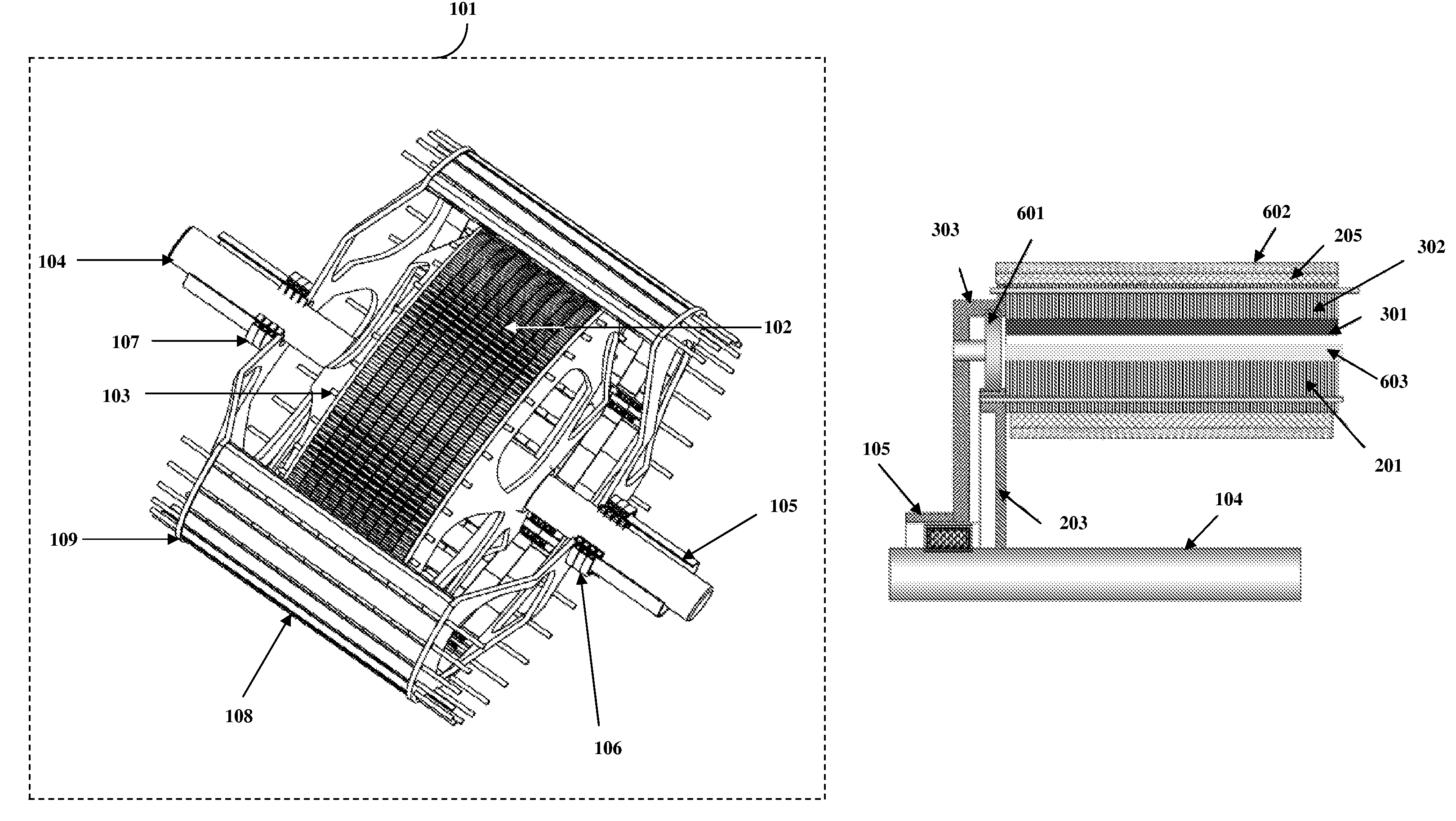
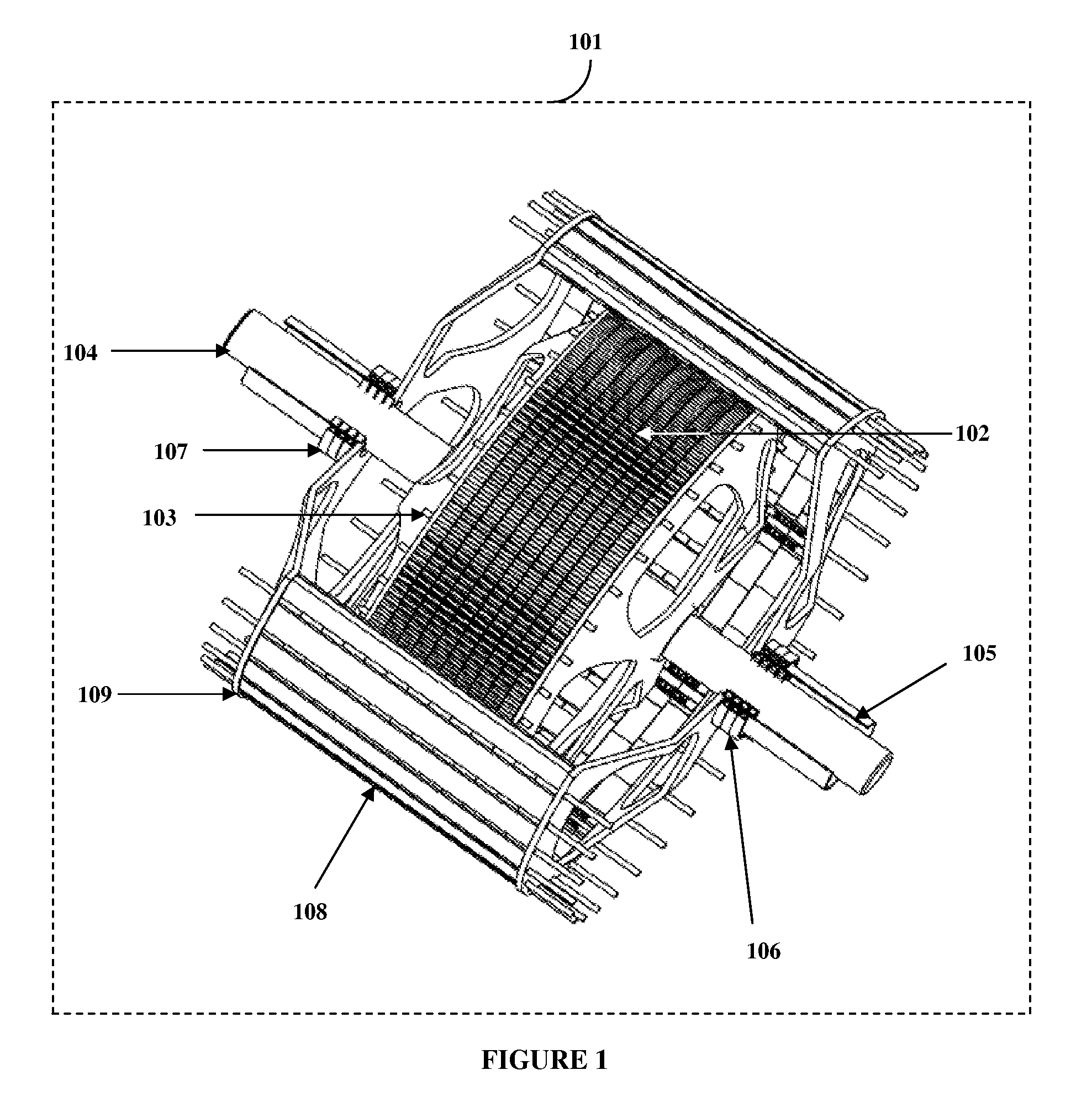
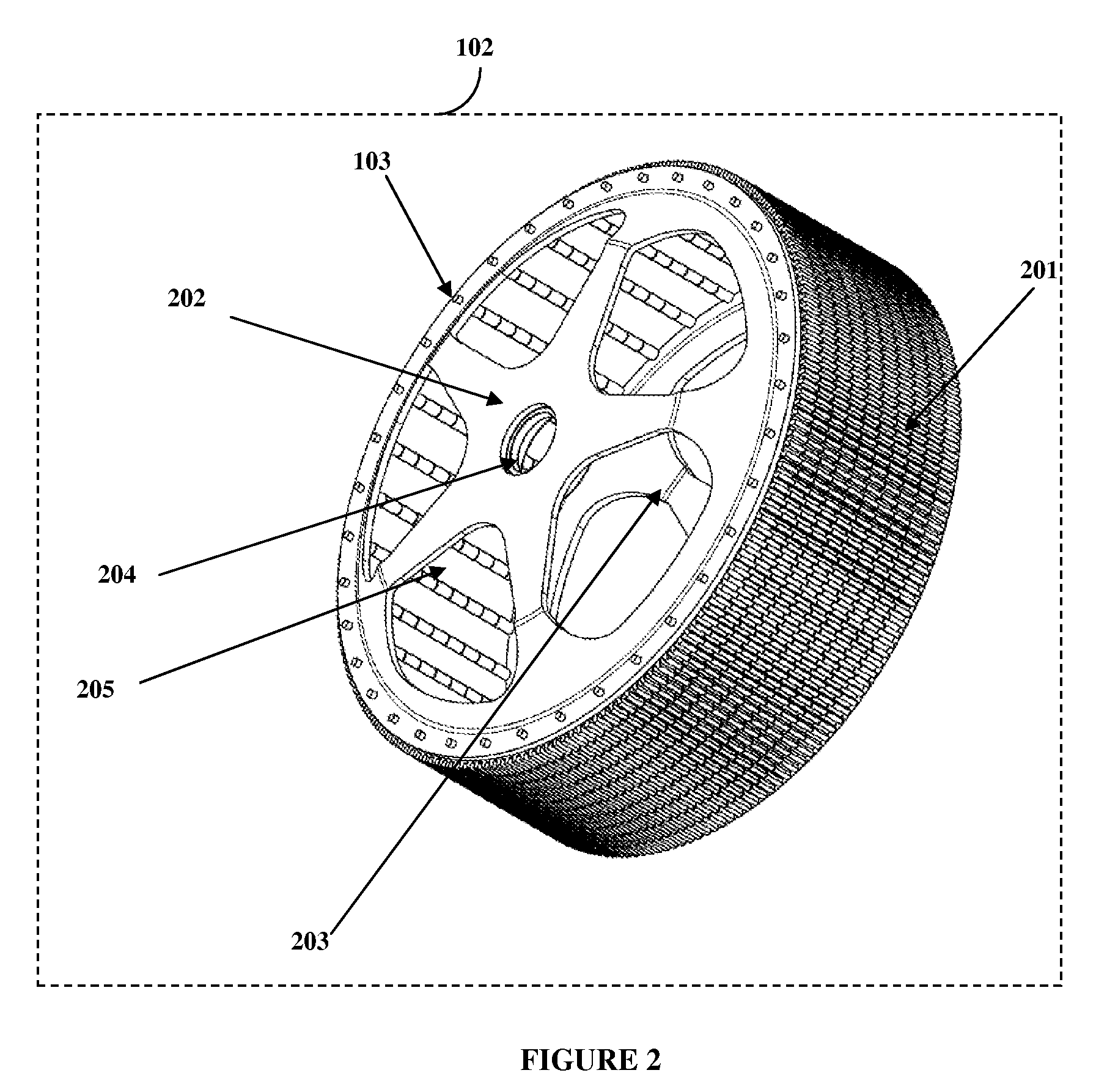
[0021]FIG. 1 exemplarily illustrates a contra rotating generator assembly. The contra rotating generator 101 comprises a cylindrical armature 102 supported on an inner shaft 104. The cylindrical armature 102 comprises current carrying elements. The inner shaft 104 rotates in a first direction. A cylindrical magnetic field rotor 108 is supported on an outer shaft 105. The outer shaft 105 is oriented coaxially to the inner shaft 104. The outer shaft 105 contra rotates in a second direction opposite to the first direction. The inner shaft 104 is driven by a first prime mover 901 and the outer shaft 105 is driven by a second prime mover 902. The coaxial inner shaft 104 and the outer shaft 105 are mounted on two inner bearings. The cross-sectional view 701 of the cylindrical armature 102 and the cross-sectional view 801 of the cylindrical magnetic field rotor 108 are illustrated in FIG. 7 and FIG. 8 respectively. The cylindrical armature 102 comprises a set of first interlocking segmente...


PUM


Abstract

Disclosed herein is an apparatus of a contra rotating generator. The contra rotating generator comprises a cylindrical armature supported on an inner shaft. The inner shaft rotates in a first direction. A cylindrical magnetic field rotor is supported on an outer shaft. The outer shaft is oriented coaxially to the inner shaft. The outer shaft contra rotates opposite to the first direction. A plurality of cam followers maintains uniform air gap between outer surface of the cylindrical armature and inner surface of the cylindrical magnetic field rotor. The uniform air gap prevents mechanical contact between the cylindrical armature and the cylindrical magnetic field rotor. A sprag clutch prevents unidirectional rotation of the inner shaft and the outer shaft. The contra rotation between the cylindrical armature and the cylindrical magnetic field rotor increases relative magnetic flux speed for generating electrical power at low speeds of operation.

Description

CROSS REFERENCE TO RELATED APPLICATIONS[0001]This application claims the benefit of provisional patent application U.S. No. 60 / 904,500 titled “Contra Rotating Generators for Multi-Megawatt Scale Wind Turbines”, filed on “Mar. 2, 2007” in the United States Patent and Trademark Office.BACKGROUND[0002]This invention, in general, relates to electrical generators. More particularly, this invention relates to a contra rotating generator apparatus for increasing relative magnetic flux speed.[0003]Electrical generators, in general, comprise a single rotating component called a rotor. The rotor may be either a coil wound armature or a magnetic field unit. The single rotating component of such electrical generators when designed for low rotational speeds, for example, in the range of 10 to 20 revolutions per minute, are large in physical dimensions and weight. Typically, in wind turbines, the power generated by the generator is proportional to the square of rotor blade diameter and hence ther...

Claims


Application Information

Patent Timeline
Patent Type & Authority Patents(United States)
IPC IPC(8): H02K16/00F03D1/02H02K7/18
CPCH02K1/24H02K1/26H02K1/2786H02K1/30H02K7/088H02K7/183H02K16/005Y02E10/725H02K7/1838H02K2213/12Y02E10/72H02K1/2791
Inventor APPA, KARIAPPA, SURI NARAYAN
Owner APPA KARI
Why Eureka
Try Eureka