
Magnetic write head having a stair notched, steep shouldered pole and a write gap bump

a write gap, stair notched technology, applied in the field of magnetic write heads, can solve the problems of reducing the strength of the magnetic write field, conflicting signals of adjacent tracks, interfering with the signal of adjacent tracks, etc., to achieve the effect of maximizing the write field strength, minimizing stray fields, and minimizing stray fields

Inactive Publication Date: 2010-03-09
WESTERN DIGITAL TECH INC
View PDF14 Cites 0 Cited by
  • Summary
  • Abstract
  • Description
  • Claims
  • Application Information

AI Technical Summary

Benefits of technology

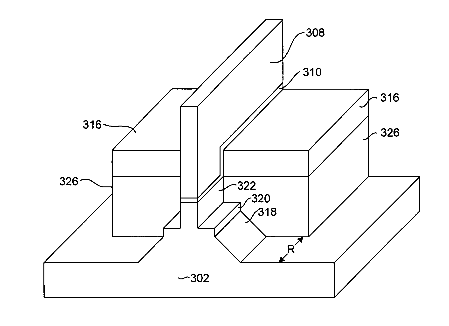
The present invention provides a magnetic write head structure that maximizes write field strength while minimizing stray fields. The write pole structure achieves this by minimizing saturation of the magnetic pole tips and preventing magnetic fields from extending laterally from the sides of the magnetic pole. The write head structure includes a write pole with a pole tip having a stair notched shape and a steep shouldered base beneath the stair notched portion. The magnetic pole can also be configured with wing shaped extensions that extend laterally from the pole tip region but which are recessed from the ABS by a desired amount. The magnetic write head structure can be manufactured by depositing materials over the magnetic pole and forming a magnetic pedestal over the magnetic pole and write gap, using ion milling to notch and trim the magnetic pole. The steep shoulder of the write pole prevents magnetic fields from emitting to the sides of the write pole while funneling as much magnetic flux to the pole tip as possible. The stair step notch helps maximize the funneling of magnetic flux to the pole tip while preventing side, stray magnetic fields. The wing shaped portions help prevent stray field writing by drawing any stray fields back into the wing shaped portions and away from the medium.

Problems solved by technology

For example, fields that extend laterally from the sides of the pole tips rather than straight from one pole to the other can result in a signal bleeding to an adjacent track and can interfere with the signal of that adjacent track.
However, in many ways these needs conflict with one another.
For example, forming a pole with a narrow track width makes it difficult to avoid choking off the flux and, therefore, reduces magnetic write field strength.
In addition, making a write pole that defines a narrow track width and which has a strong magnetic write field can promote stray side fields which can cause adjacent track intereference.

Method used


Image

  • Magnetic write head having a stair notched, steep shouldered pole and a write gap bump
  • Magnetic write head having a stair notched, steep shouldered pole and a write gap bump
  • Magnetic write head having a stair notched, steep shouldered pole and a write gap bump

Examples


Embodiment Construction

[0023]The following description is of the best embodiments presently contemplated for carrying out this invention. This description is made for the purpose of illustrating the general principles of this invention and is not meant to limit the inventive concepts claimed herein.

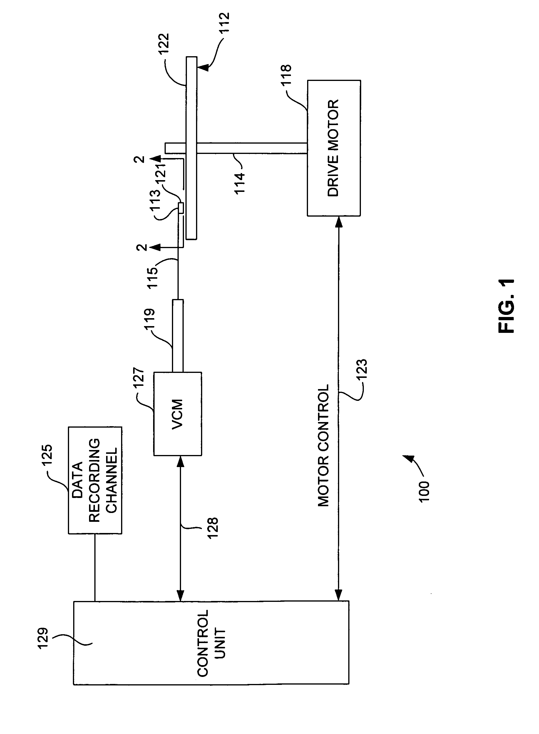
[0024]Referring now to FIG. 1, there is shown a disk drive 100 embodying this invention. As shown in FIG. 1, at least one rotatable magnetic disk 112 is supported on a spindle 114 and rotated by a disk drive motor 118. The magnetic recording on each disk is in the form of annular patterns of concentric data tracks (not shown) on the magnetic disk 112.

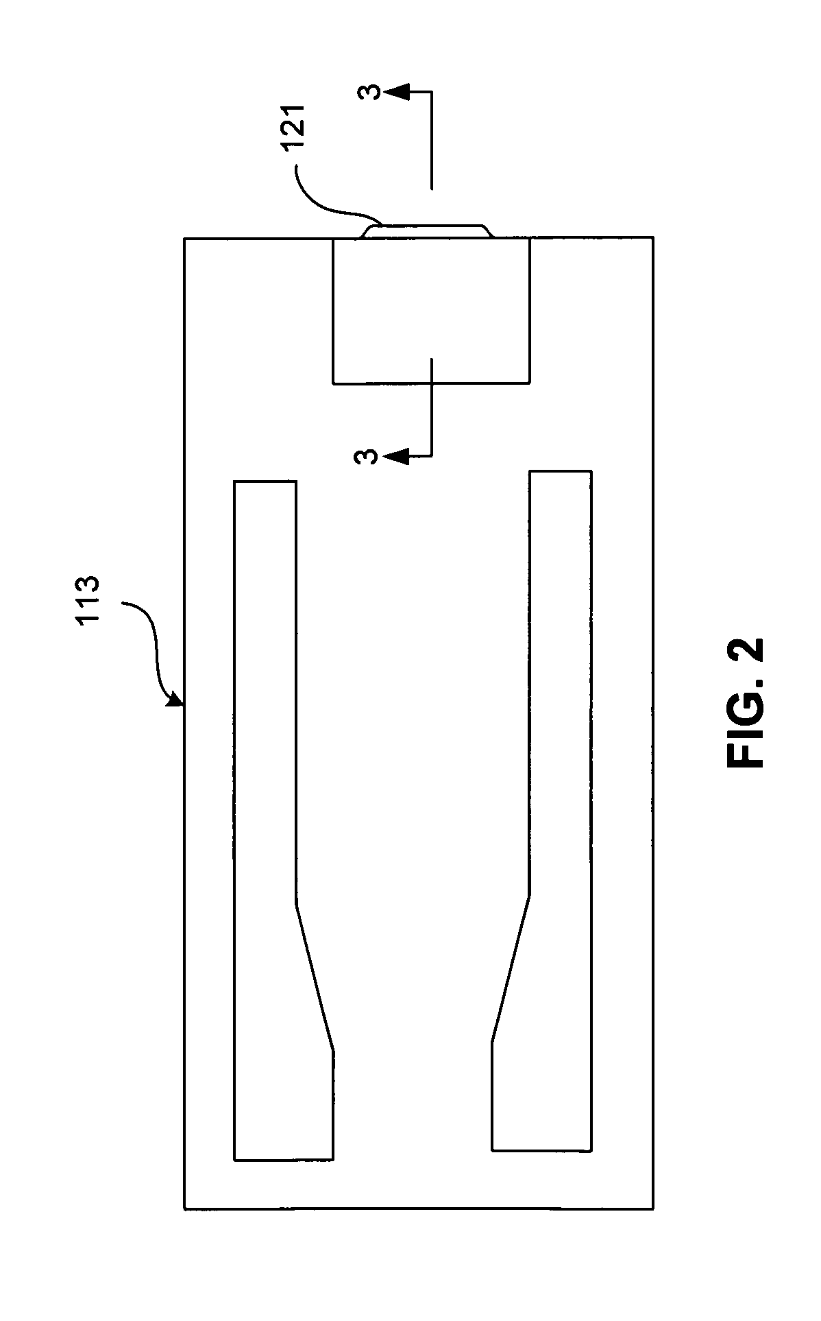
[0025]At least one slider 113 is positioned near the magnetic disk 112, each slider 113 supporting one or more magnetic head assemblies 121. As the magnetic disk rotates, slider 113 moves radially in and out over the disk surface 122 so that the magnetic head assembly 121 may access different tracks of the magnetic disk where desired data are written. Each slider 1...


PUM

PropertyMeasurementUnit
angleaaaaaaaaaa
angleaaaaaaaaaa
distanceaaaaaaaaaa

Abstract

A magnetic write head structure that maximizes write field strength while minimizing stray fields. The write pole structure maximizes write field strength by minimizing saturation of the magnetic pole tips, and minimizes stray field writing by preventing magnetic fields from extending laterally from the sides of the magnetic pole. The write head structure includes a write pole having a pole tip configured with a stair notched shape and a steep shouldered base beneath the stair notched portion. This configuration maximizes the amount of flux that can be delivered to the pole tip while also avoiding stray fields. The magnetic pole can also be configured with wing shaped extensions that extend laterally from the pole tip region but which are recessed from the ABS by a desired amount. The magnetic write head structure can be manufactured by forming a magnetic pole with a raised portion, depositing a write gap material over the magnetic pole and then forming a magnetic pedestal over the magnetic pole and write gap, the pedestal having a width significantly smaller than the width of the raised portion of the magnetic pole, a first ion mill can then be performed to notch and trim the magnetic pole. Then a non-magnetic layer such as alumina can be deposited and a second ion mill performed to form a stair notched configuration. An alumina bump can be formed prior to ion milling to provide a mask for forming the laterally extending, recessed wings in the pole tip of the magnetic pole.

Description

FIELD OF THE INVENTION[0001]The present invention relates to magnetic write heads for magnetic data recording, and more particularly to a magnetic write head having a narrow P1 pole with a stepped notch and a sloping shoulder, and having a bump formed in the write gap, all for improved magnetic performance.BACKGROUND OF THE INVENTION[0002]The heart of a computer's long term memory is an assembly that is referred to as a magnetic disk drive. The magnetic disk drive includes a rotating magnetic disk, write and read heads that are suspended by a suspension arm adjacent to a surface of the rotating magnetic disk and an actuator that swings the suspension arm to place the read and write heads over selected circular tracks on the rotating disk. The read and write heads are directly located on a slider that has an air bearing surface (ABS). The suspension arm biases the slider into contact with the surface of the disk when the disk is not rotating but, when the disk rotates, air is swirled...

Claims


Application Information

Patent Timeline
Patent Type & Authority Patents(United States)
IPC IPC(8): G11B5/31G11B5/187
CPCG11B5/1278G11B5/3116G11B5/3163
Inventor GUTHRIE, HUNG-CHINHSIAO, WEN-CHIEN DAVIDLO, JYH-SHUEYPENTEK, ARON
Owner WESTERN DIGITAL TECH INC
Learn More