Pulse Generating System for Electrostatic Precipitator

a technology of pulse generator and electrostatic precipitator, which is applied in the direction of pulse technique, corona discharge, instruments, etc., can solve the problems of increasing detector cost of pulse system, reducing the voltage applied to the electrostatic precipitator and re-entraining dust particles back, and affecting the performance of the electrostatic precipitator energized dust particles, etc., to achieve the effect of enhancing the efficiency of the transformer cor

Active Publication Date: 2008-08-14
FLSMIDTH AS
View PDF27 Cites 2 Cited by
  • Summary
  • Abstract
  • Description
  • Claims
  • Application Information

AI Technical Summary

Benefits of technology

[0010]It is therefore an object of the invention to provide pulse generating system with enhanced efficiency. It is moreover an object of the invention to provide a pulse generating system with a transformer, wherein saturation of the core of the transformer is alleviated. It is moreover an object of the invention to provide a system with enhanced protection of the switching device.
[0012]In a preferred embodiment the system further comprises a transformer with a primary and a secondary winding, where the first power supply, the storage capacitor, the switching device and the parallel-coupled anti-parallel rectifier device are coupled to the primary winding of the transformer; where the second power supply and a coupling capacitor are coupled to the secondary winding of the transformer; and where the system is arranged to be coupled to the electrostatic precipitator via the coupling capacitor. Hereby, an advantageous embodiment of the system adapted to pulse generating systems of the type comprising a transformer is provided. The storage capacitor is charged by the first power supply to a suitable voltage level and the second power supply generates a base DC high voltage. The coupling capacitor prevents a short circuit of the second power supply by the secondary winding.
[0017]According to a preferred embodiment of the invention, the system further comprises a clamping circuit connected to the junction between the storage capacitor and the power supply. Thus, the clamping circuit is connected as close as possible to the switching device. Hereby, a path for the current caused by the energy stored in the system (viz. in the leakage inductance of the pulse transformer) is created when the switching device is turned off, thus protecting the switching device by limiting the voltage across it, if the capacitor in the clamping network has a high value. Moreover, the clamping circuit minimizes the saturation of the pulse transformer in the case of sparks, as it takes energy from the system. Preferably, the clamping circuit comprises a diode in series with a capacitor and a resistor in parallel with the diode. The capacitor serves to limit the voltage across the switch during turn-off and the resistor serves to limit the current during discharging of the clamping capacitor when the switch is turned on.
[0021]Finally, it is preferred that the system according to the invention further comprises a bias network connected to the primary winding of the transformer, where the bias network comprises a voltage source, a limiting resistor and a bias choke. The bias network enhances the efficiency of the transformer core in that it can be magnetized in two polarities; hereby, a smaller and thus cheaper transformer core can be used.

Problems solved by technology

The performance of an electrostatic precipitator energized can be impaired when treating high resistivity dust particles.
The result is a decreased voltage applied to the electrostatic precipitator and re-entrainment of the dust particles back to the gas stream due to small eruptions on the dust layer.
However, this detector is increasing the cost of the pulse system.
Moreover, neither U.S. Pat. No. 4,600,411 nor U.S. Pat. No. 4,854,948 addresses the problem that the core of the transformer becomes saturated upon sparks inside the electrostatic precipitator, which aggravates the operation of the electrostatic precipitator substantially.
Finally, the switching devices in the known systems are subject to potentially damaging high rates of di / dt in the case of sparks taking place in the electrostatic precipitator, hereby shortening the life times thereof.

Method used


Image

  • Pulse Generating System for Electrostatic Precipitator
  • Pulse Generating System for Electrostatic Precipitator
  • Pulse Generating System for Electrostatic Precipitator

Examples


Embodiment Construction

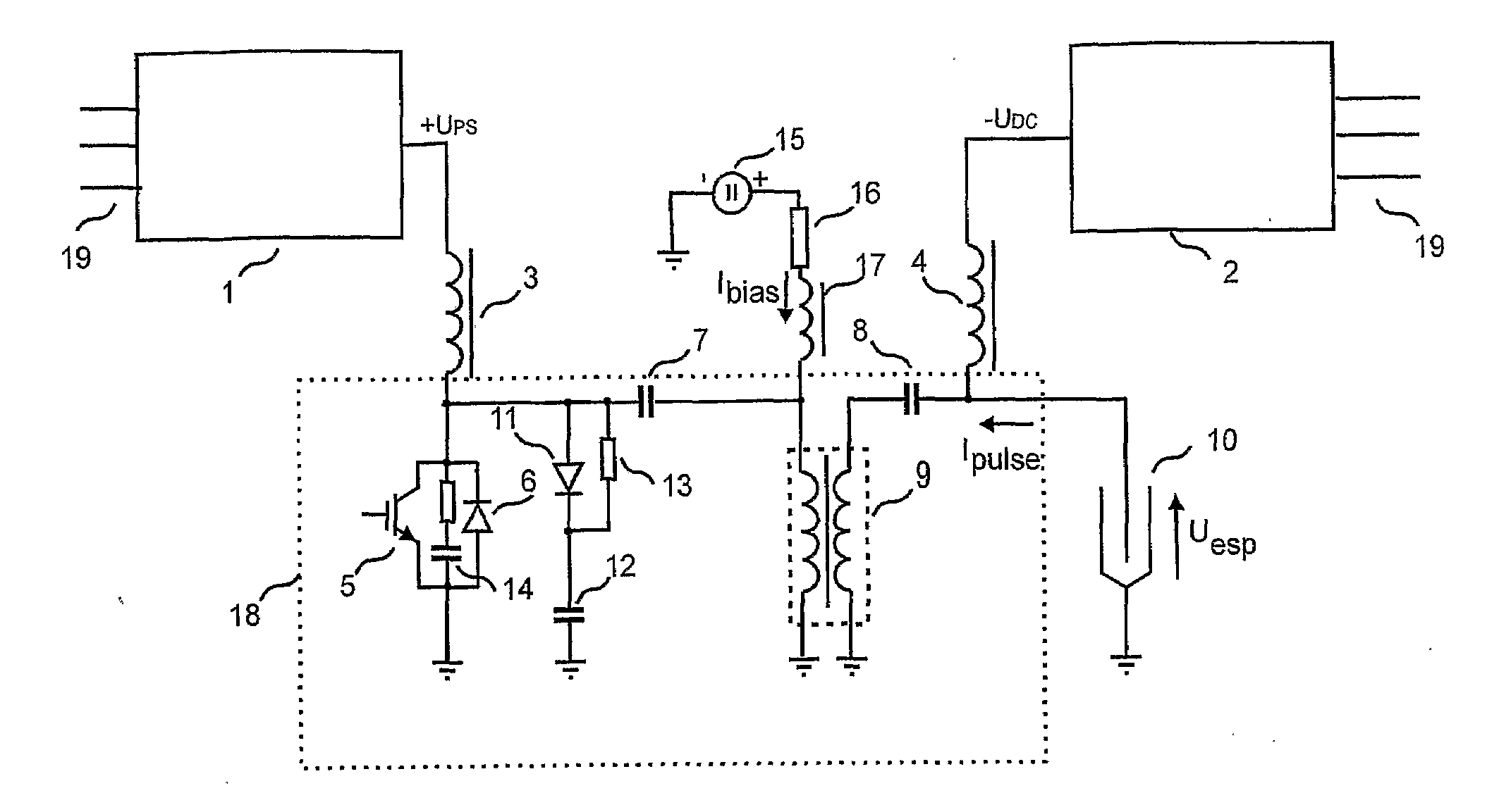
[0031]FIG. 1 is a block diagram of the pulse system according to the invention. Shown is a first power supply 1, hereinafter referred to as pulse power supply 1, and a second power supply 2, hereinafter referred to as DC power supply 2, arranged to energize an electrostatic precipitator 10. The DC power supply 2 is arranged to pre-charge the electrostatic precipitator 10 to a DC voltage, typically in the range of a 25-50 kilovolts. Both power supplies 1, 2 are fed from a three-phase power line 19.

[0032]The reference number 18 denotes the main circuit of the system according to the invention. FIG. 1 moreover shows that the pulse power supply 1 is connected to one terminal of a storage capacitor 7 through a filtering choke 3, whilst the other terminal of the storage capacitor 7 is connected to one terminal of a primary winding of a transformer 9. The other terminal of the primary winding of the transformer 9 is connected to a common terminal. The common terminal could be grounded or n...


PUM


Abstract

The invention relates to a pulse generating system for generating high voltage pulses to energize an electrostatic precipitator (10), said system comprising: a first power supply (1) and a second power supply (2), where said second power supply (2) is arranged to pre-charge said electrostatic precipitator (10) to a DC voltage; a storage capacitor (7) and a series inductance; a switching device (5) coupled in parallel with an anti-parallel rectifier device (6); and wherein said system is arranged to be coupled to said electrostatic precipitator. The invention relates to provide such a pulse generating system with enhanced efficiency compared to present pulse generating systems and with enhanced protection of the components of the system in case of sparks in the electrostatic precipitator (10). This is achieved, when the switching device (5) of the system has turn-off capability and when the system comprises a clamping circuit (11-13; 60-67).

Description

FIELD OF THE INVENTION[0001]This invention relates to a pulse generating system for generating high voltage pulses to energize an electrostatic precipitator (ESP), said system comprising a first power supply and a second power supply, where said second power supply is arranged to pre-charge said electrostatic precipitator to a DC voltage; a storage capacitor and a series inductance; and a switching device coupled in parallel with an anti-parallel rectifier device; wherein said system is arranged to be coupled to said electrostatic precipitator.BACKGROUND OF THE INVENTION[0002]Electrostatic precipitators can be used for collection and thus removal of particulate from a gas stream in industrial processes. The density of particles in the gas stream can be reduced significantly by charging the particles by, via the discharge electrode of the electrostatic precipitator, generating charge carriers to become attached to the particles in the gas stream, and by applying a high voltage field ...

Claims


Application Information

Patent Timeline
IPC IPC(8): B03C3/68
CPCB03C3/68Y10S323/903H03K17/00
Inventor REYES, VICTORTAARNING, CLAUS
Owner FLSMIDTH AS
Why Eureka
Try Eureka