
Method and device for wheel camber adjustment

a technology for camber adjustment and wheel camber, which is applied in the direction of pivoted suspension arms, transportation and packaging, construction cranes, etc., can solve the problems of unfavorable driving behavior of the vehicle, unfavorable driver manual camber adjustment, and adjustment of camber angl

Inactive Publication Date: 2010-03-09
CNH BAUMASCHEN
View PDF16 Cites 26 Cited by
  • Summary
  • Abstract
  • Description
  • Claims
  • Application Information

AI Technical Summary

Benefits of technology

"The present invention is about a method and device for adjusting the camber angle of wheels in commercial vehicles, particularly graders. The invention aims to improve the tracking and steering of the vehicle, as well as reduce the turning circle of the vehicle. The current manual adjustment method is not optimal for the driver's task and can lead to reduced efficiency and safety. The invention provides an automatic camber adjustment system that is triggered by driving parameters such as the axle swing angle, steering lock angle, lateral forces, and the absolute inclination of the vehicle in relation to a horizontally-aligned carriageway. The system uses sensors to detect these parameters and a computer control unit to adjust the camber angle accordingly. The invention improves the driver's ability to control the vehicle and increases safety while driving on uneven ground."

Problems solved by technology

A disadvantage of this existing design is that the camber angle is also adjusted as a function of the swing angle of the front axle, as the front axle and camber cylinder are directly connected to each other.
It is noted that the initial working path is completed at a camber angle which is unfavourable to the driving behavior of the vehicle.
This is due to the fact that the driver cannot carry out manual camber adjustment and adjust the functions of the machine at the same time.

Method used


Image

  • Method and device for wheel camber adjustment
  • Method and device for wheel camber adjustment
  • Method and device for wheel camber adjustment

Examples


Embodiment Construction

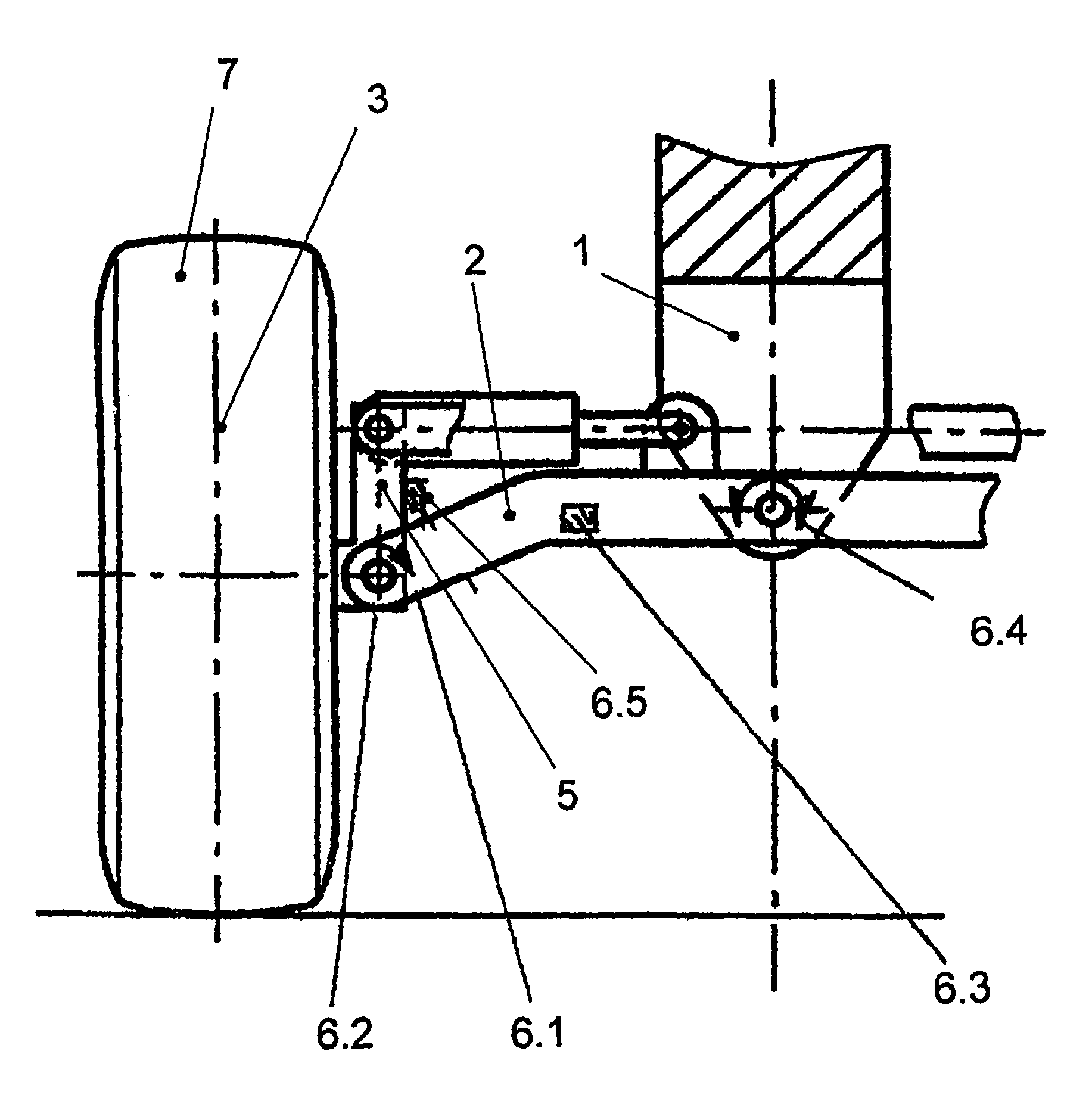
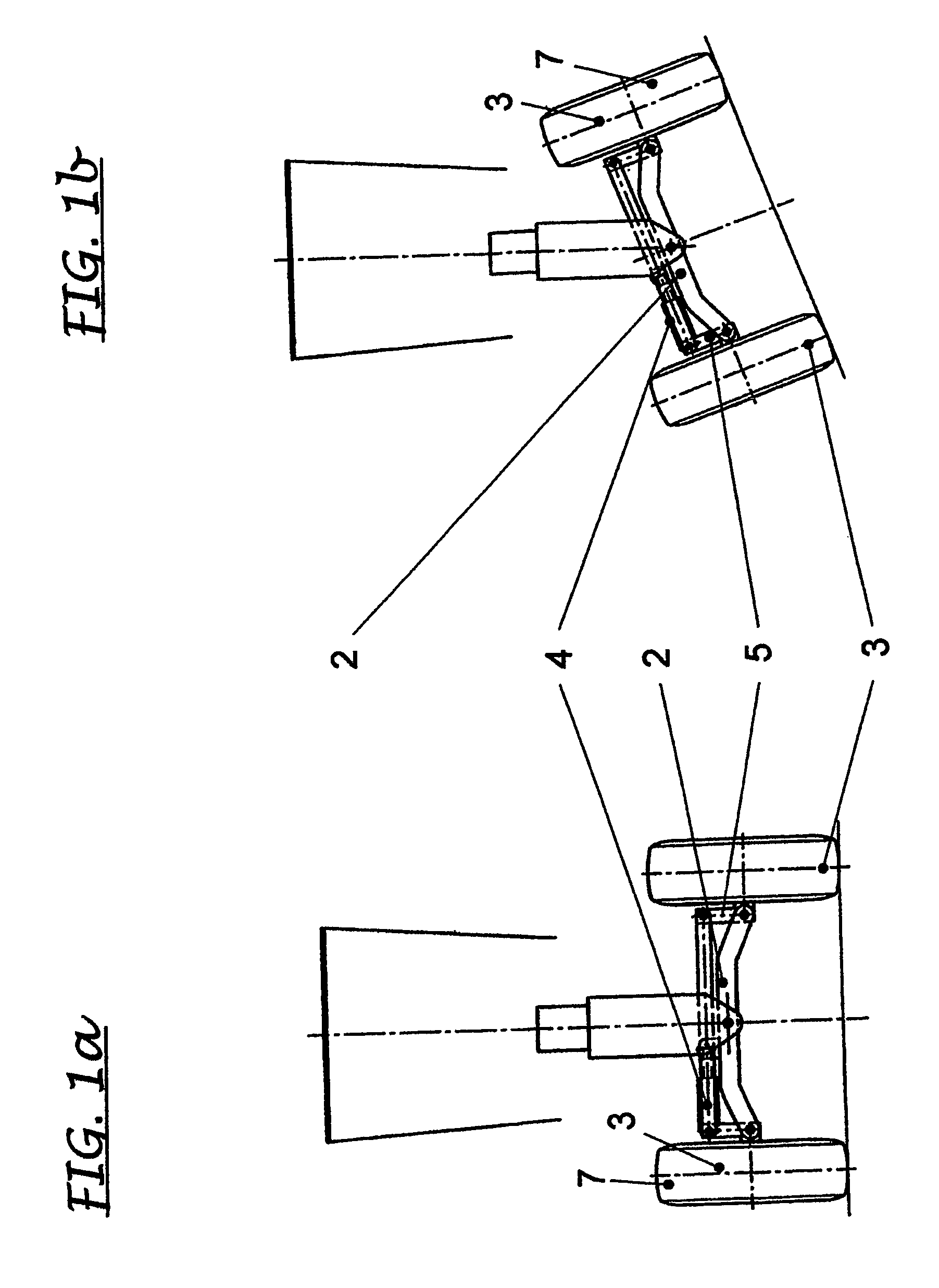
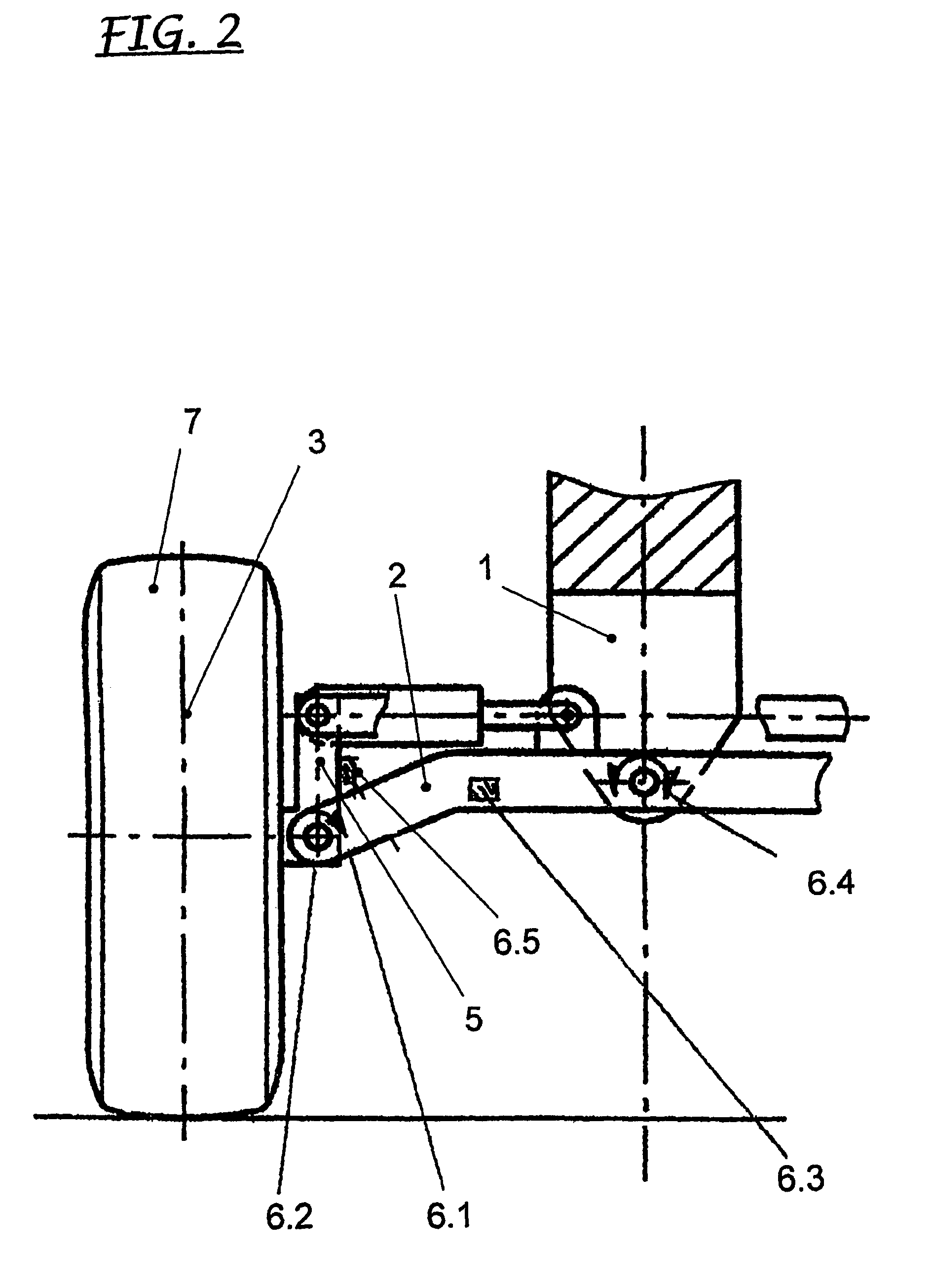
[0026]FIG. 1a and FIG. 1b illustrate the camber adjustment system in accordance with the present invention. In this case, the camber angle is adjusted manually by means of a camber cylinder 4, which is mechanically connected to a wheel pivot unit 5. The wheel pivot unit 5 is moved by the extension and retraction of the camber cylinder 4 and the relative angle between the wheel plane 3 of the vehicle wheel and the perpendicular of the carriageway is thus changed. The camber cylinder 4 has a releasable connection with the front axle 2 and is arranged in parallel to the latter and to the carriageway. If there is a terrain-dependent inclination of the carriageway, the front axle 2 and the camber cylinder 4 arranged in parallel to it will follow the inclination of the carriageway. The camber cylinder 4 and the wheel pivot unit 5 are at right angles to each other in the case of both a flat and an inclined carriageway. The camber angle is the same in both cases.

[0027]FIG. 2 shows the advan...


PUM


Abstract

The invention concerns a method and a device for the adjustment of wheel camber in commercial vehicles, particularly wheeled construction vehicles used for earthworks, particularly on uneven ground. The camber angle is set inventively and automatically by means of a camber cylinder and a wheel pivot unit, as a function of at least one of the driving parameters. For this purpose, the driving parameters, e.g. the axle swing angle, the steering lock angle, the lateral force on the vehicle wheels on the front axle and the absolute inclination of the construction vehicle are detected by sensors, the output signals of which are fed to an electronic control unit as input parameters. The camber angle sets itself as a function of the setting signal from the electronic control unit by means of a camber cylinder and a wheel pivot unit, in accordance with specified control strategies. As well as the self-setting wheel camber adjustment system, the camber cylinder is embodied so that it can still be operated manually.

Description

FIELD OF THE INVENTION[0001]The present invention concerns a method and a device for the adjustment of wheel camber in commercial vehicles, particularly wheeled construction vehicles used for earthworks, particularly on uneven ground.BACKGROUND OF THE INVENTION[0002]The kinematics of the chassis when load changes occur, traversing curves and earthworks with loads acting at right angles to the direction of travel, which contribute to directional stability and adhesion, are becoming the focus of further developments with the trend towards higher speeds of travel, increased productivity and greater convenience.[0003]In graders, the chassis is particularly characterized by: the wheelbase, the gauge, the toe-in and camber behavior and other important key variables.[0004]The camber, or relative inclination of the wheel plane to the perpendicular of the carriageway, assumes particular significance for tracking and steering, as a negative camber increases the force acting at right angles to...

Claims


Application Information

Patent Timeline
Patent Type & Authority Patents(United States)
IPC IPC(8): B60G3/26B62D17/00B60G7/00B60G9/02B60G17/019B60G21/00B62D9/02
CPCB60G7/006B60G9/02B60G17/01908B60G21/007B62D9/02B62D17/00B60G2200/322B60G2200/46B60G2300/06B60G2300/08B60G2300/09B60G2400/25B60G2800/0194
Inventor DAMM, JURGEN
Owner CNH BAUMASCHEN
Learn More