
Aerosol valve actuator

a valve actuator and valve body technology, applied in the direction of liquid transfer devices, single-unit apparatuses, manufacturing tools, etc., can solve the problems of unsanitary, messy, fully satisfactory, accumulation of post-foaming products within the actuator body, etc., to achieve reliable and efficient function, strong construction, and easy manufacturing and assembly

Inactive Publication Date: 2006-07-13
PRECISION VALVE CORP
View PDF16 Cites 14 Cited by
  • Summary
  • Abstract
  • Description
  • Claims
  • Application Information

AI Technical Summary

Benefits of technology

The present invention provides an aerosol valve actuator that avoids the post-foaming problem, which means that no unsightly, unsanitary, and messy product occurs outside the actuator outlet after actuation ceases, and no post-foaming product accumulates within the actuator in a manner that is not removed on the next actuation. The actuator is constructed in a reliable and efficient manner, and it functions easily and reliably. The actuator includes an enclosure, an aerosol valve stem engaging portion, a product dispensing opening, and a flexible and expandable product conduit extending between the valve stem engaging portion and the product dispensing opening. The actuator is designed to mold the product conduit of a softer plastic material than the remainder of the actuator, which ensures that the post-foaming product does not expand outside the actuator outlet after actuation ceases. The actuator can be easily assembled and disassembled, and it is constructed in a way that prevents any unsanitary or messy product from occurring.

Problems solved by technology

This is not only an aesthetic issue, but is also unsanitary, messy, and generally requires wiping away the foamed product outside the outlet before the next dispensing of product.
Such means have not been fully satisfactory, can be overly complex and can result in the accumulation of post-foaming product within the actuator body.

Method used


Image

  • Aerosol valve actuator
  • Aerosol valve actuator
  • Aerosol valve actuator

Examples


Embodiment Construction

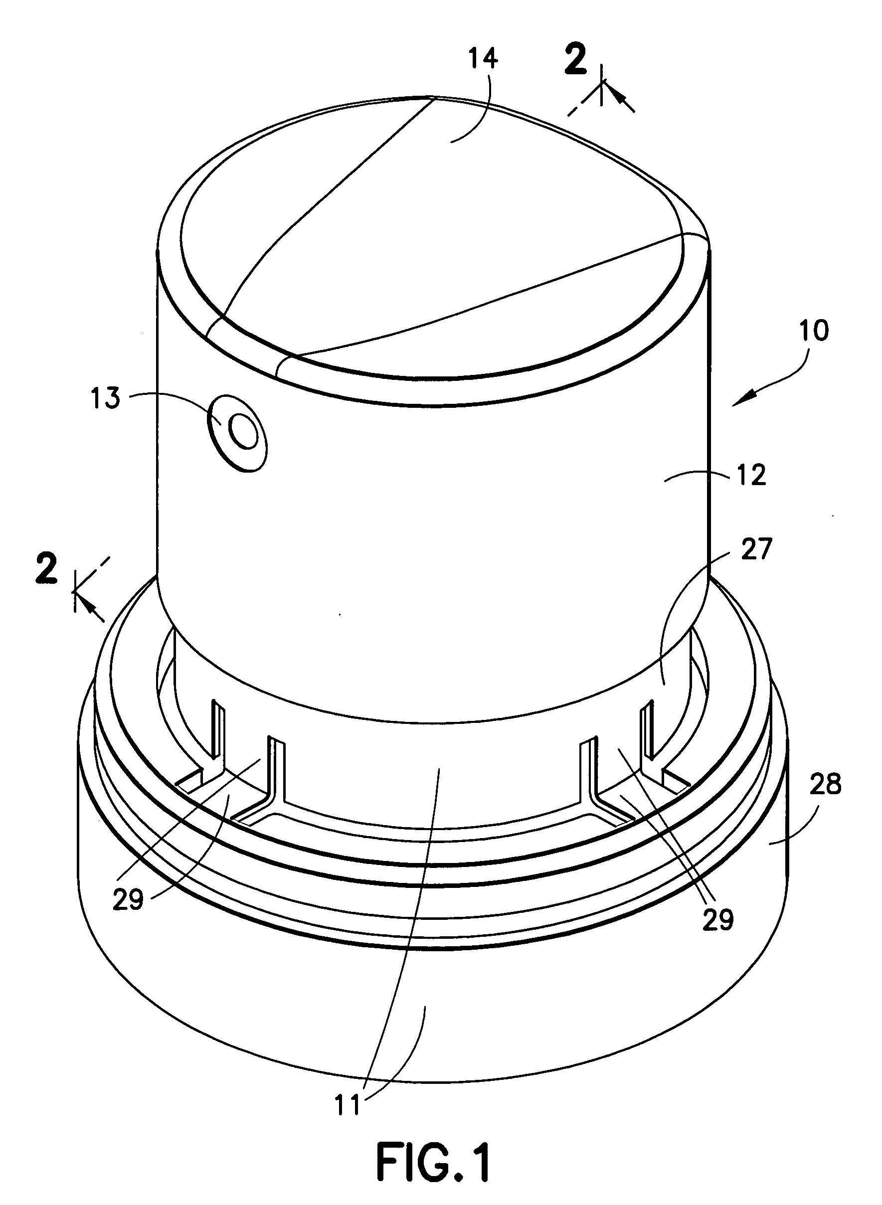
[0025] Referring to FIG. 1, aerosol valve actuator 10 is shown assembled from molded plastic base 11 and cap 12. Cap 12 has a product dispensing opening 13 in its side wall, and a top surface 14 for finger actuation of the actuator by pressing downward.

[0026]FIGS. 2-5 are axial cross-sectional views of the assembled actuator of FIG. 1 in various operational positions of the cap 12 in relation to the base 11. Base 11 is shown mounted on the mounting cup 15 of an aerosol container 16 by base flange 17 that snaps under edge 18 of the mounting cup (see FIG. 2). Mounting cup 15 supports an aerosol valve with aerosol valve stem 19 in known fashion.

[0027] Base 11 is shown by itself in perspective in FIG. 6 and in axial cross-section in FIG. 9. Referring to FIG. 9, base 11 has side wall 20 with a product dispensing opening 21 therein. Base 11 includes a centrally located tube 22 with bottom region 23 for engagement with the aerosol valve stem 19 (see FIG. 2). Extending between bottom regi...


PUM

PropertyMeasurementUnit
flexibleaaaaaaaaaa
pressureaaaaaaaaaa

Abstract

An aerosol valve actuator with a valve stem engaging portion, product dispensing opening, and flexible and expandable product conduit between the engaging portion and dispensing opening. The product conduit is molded at least in part of a first expandable flexible plastic material softer than a second plastic material of the remainder of the actuator. The remainder of the actuator is first molded, followed by molding the first plastic material to form at least a part of the product conduit. After the actuator has been actuated to dispense a foaming product and actuation ceases, the post-foaming product expands within the product conduit since the conduit expands to absorb the product expansion. Actuator cap and base product dispensing side openings align only during valve actuation. Base inwardly flexible members and cap internal ramps bias the cap upwardly when actuation ceases. Base upper portion telescopes in base lower portion during actuation.

Description

[0001] This application is a division of U.S. application Ser. No. 10 / 738,855 filed Dec. 17, 2003. Applicant claims the benefit of the prior U.S. application.FIELD OF THE INVENTION [0002] The present invention relates to aerosol valve actuators, and more particularly to such actuators of the enclosure type for use with products that expand and foam when first exposed to air. BACKGROUND OF THE INVENTION [0003] Aerosol valve actuators of the enclosure type generally have the enclosure base mounted onto the product container and / or onto the mounting cup of the aerosol valve on the container. Finger actuatable means on the actuator are operationally associated with the aerosol valve stem for actuating the aerosol valve and dispensing the product. The finger actuatable means may be for example a hinged finger pad integrally molded as one piece with the remainder of the actuator and extending into an opening in the upper portion of the actuator; or, may be a separate cap member on a base ...

Claims


Application Information

Patent Timeline
Patent Type & Authority Applications(United States)
IPC IPC(8): B65D83/14B65D83/16B67D7/32
CPCB65D83/753B65D83/206B65D83/205B05B11/1053
Inventor KOLANUS, GUNTER
Owner PRECISION VALVE CORP
Learn More