Rheometer

a rheometer and rheological technology, applied in the field of rheometers, can solve the problems of affecting the measurement accuracy, so as to prevent the formation of a sliding layer and prevent excessive demixing phenomena in the material

Active Publication Date: 2010-03-09
KARLSRUHER INST FUR TECH +1
View PDF13 Cites 0 Cited by
  • Summary
  • Abstract
  • Description
  • Claims
  • Application Information

AI Technical Summary

Benefits of technology

[0007]This object is achieved in accordance with the invention with a rheometer having the features of the independent claim. The profile on the inner wall of the container is thereby formed by at least one and, in particular, several profile elements which are exchangeably fastened to the container. The user can thereby select the type and dimensions of the profile in dependence on the material to be investigated, and mount corresponding profiling elements on the container. It is thereby possible to reliably prevent formation of a sliding layer on the surface of the inner wall of the container through suitable selection of the profile geometry, wherein the profile also prevents excessive demixing phenomena in the material.
[0015]When the rheometer is used to determine the rheological characteristic values of building materials, such as mortar or concrete, the holder of the exchangeable profiling elements must be relatively stable and have a simple construction, since the material to be investigated could otherwise impair the holder and, in particular, the exchangeability of the profiling elements. In a preferred embodiment of the invention, the container therefore has several holes in its wall, into each of which a profiling element can be inserted from the outer side of the container. The profiling elements are thereby preferably positively held in their inserted position in that e.g. defined abutment surfaces come into contact. This profiling element holder is advantageous in that it must only be forced radially outwardly and thereby be pushed out of the holes in the wall of the container in order to exchange it. In the inserted state, the profiling elements are tightly fitted in the holes to prevent formation of gaps into which the material to be investigated could enter.
[0016]Excessive motion of the profiling elements towards the center of the inner space of the container is positively prevented as mentioned above. During operation, a locking element should additionally be provided on the outer side of the container to keep the inserted profiling elements in their position. Each profiling element may have its own separate outer locking element. In a design with particularly simple construction in accordance with the invention, all profiling elements have one single common locking element, which may e.g. be an outer cup into which the container can be tightly fitted. In this case, the profiling elements are substantially flush with the outer side of the container when they are inserted into the holes of the wall of the container, such that the container with inserted profiling elements can be inserted into the outer cup.

Problems solved by technology

In particular, in polydisperse suspensions, such as e.g. fresh building material suspensions, the metrological determination of the rheological properties is problematic, in particular, due to local demixing and associated sliding phenomena.
These demixing phenomena can cause a very distinct localized change in the composition and thereby in the rheological properties of the material sample, and substantially falsify the measurement result.
Since the groove structure is an integral component of the container, the profile cannot be adjusted to the material to be investigated.

Method used


Image

  • Rheometer
  • Rheometer
  • Rheometer

Examples


Embodiment Construction

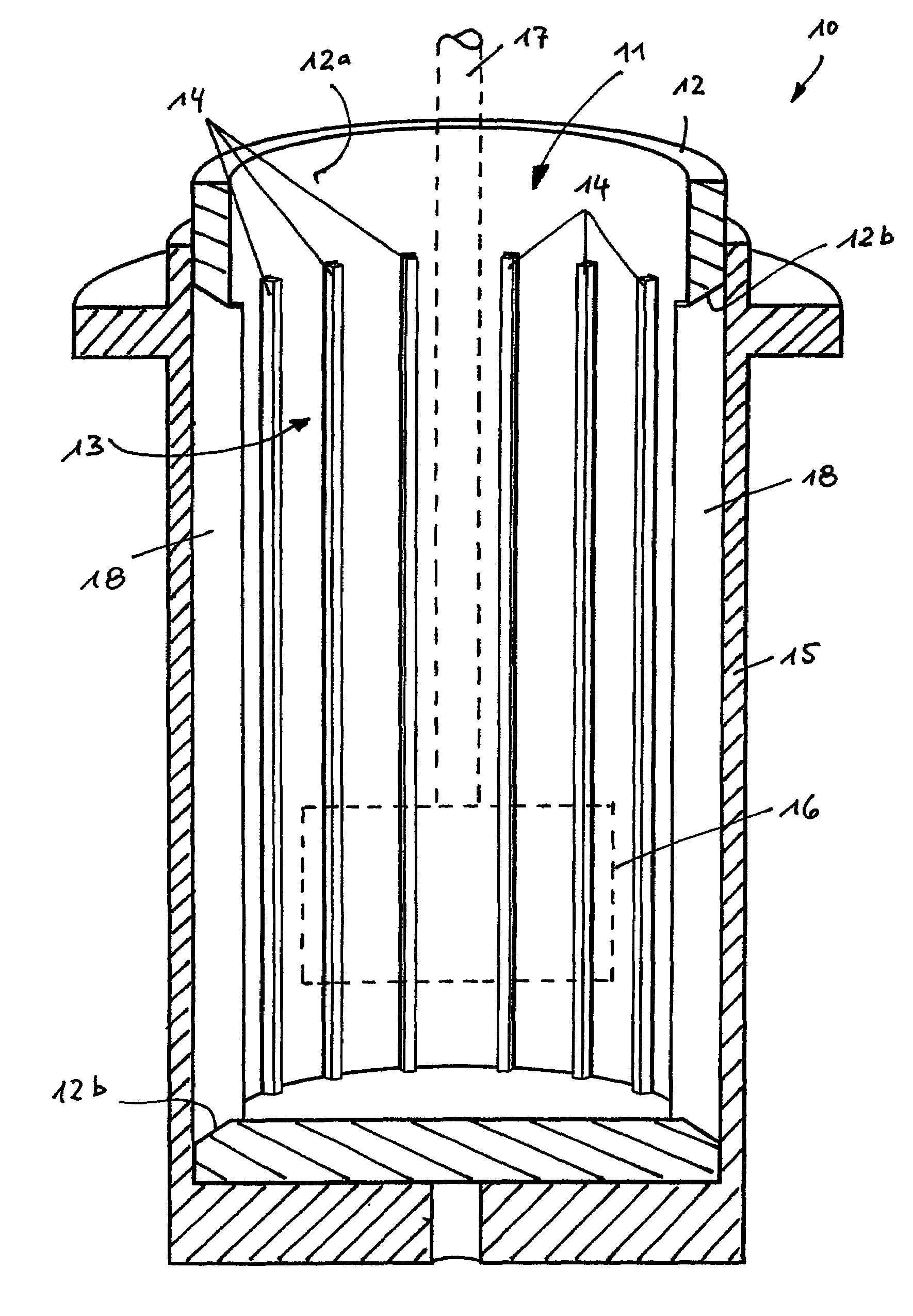
[0022]FIG. 1 shows a section of the construction of a rheometer 10 comprising a cup-shaped container 12 which is open to the top and has a circular cross-section in the embodiment shown. A material sample to be investigated (not shown) can be filled into the inner space 11 of the container 12.

[0023]A vertical rotary driven measuring shaft 17 (shown as dashed lines) extends to the inner space 11 of the container 12 and has a rotor 16 at its lower end, which may have any shape or a shape which is adjusted to the material to be investigated.

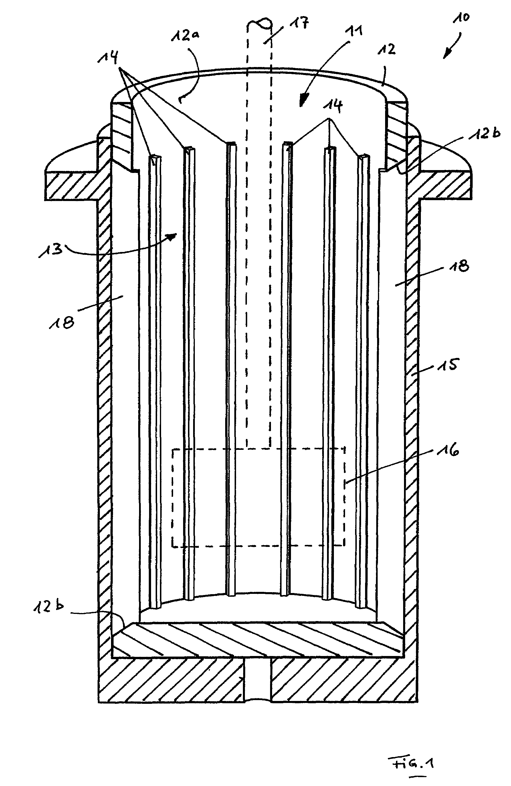
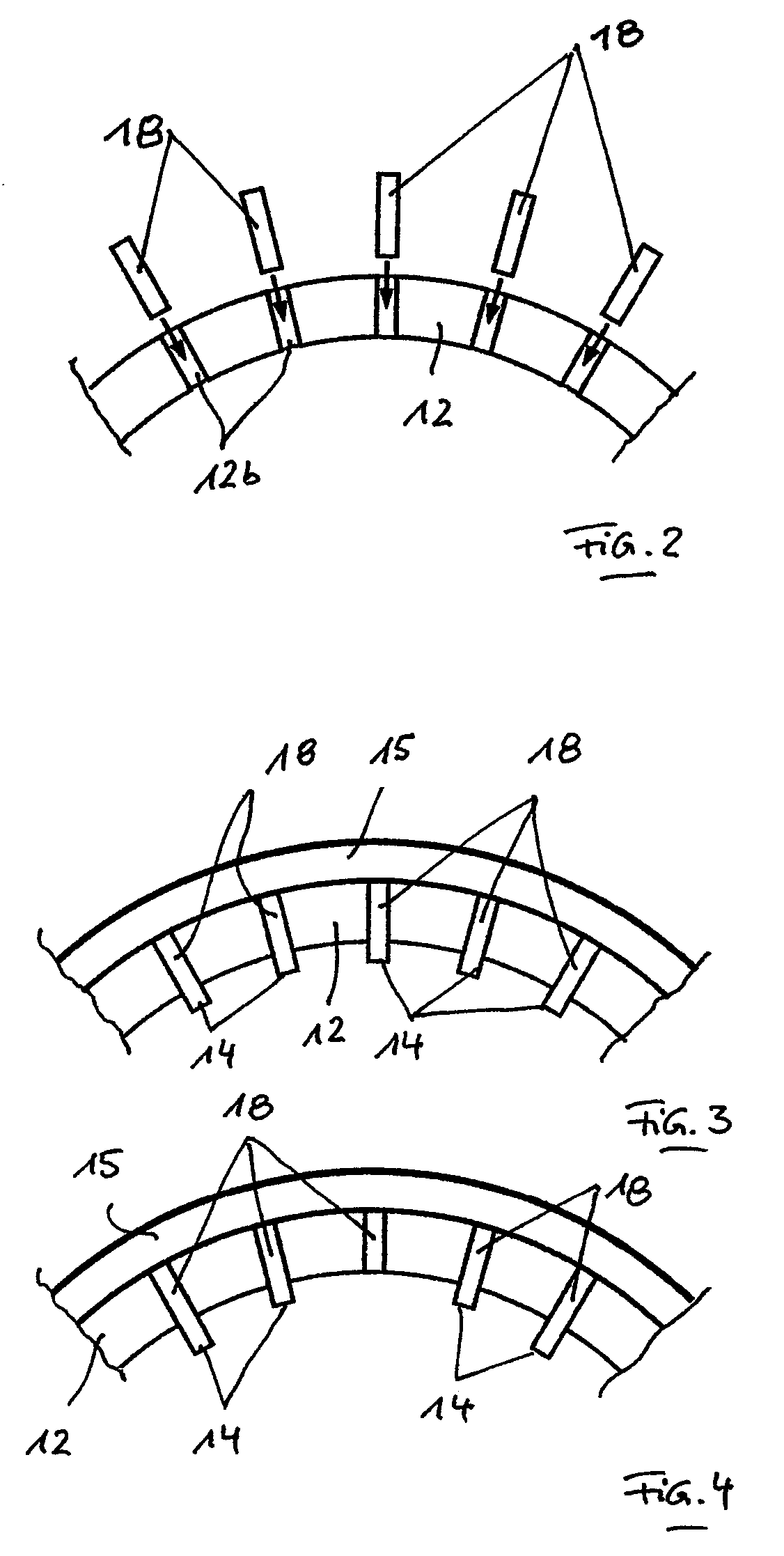
[0024]A profile 13 is provided on the inner wall 12a of the container 12, which is formed by a plurality of strip-shaped ribs 14 which are distributed about the inner periphery of the container 12. Each rib 14 extends from the vicinity of the bottom of the container 12 to its upper area and extends substantially parallel to the measuring shaft 17 and thereby substantially vertically.

[0025]Each rib 14 is part of a lamella 18 that is exchangeably held...


PUM

PropertyMeasurementUnit
depthaaaaaaaaaa
heightaaaaaaaaaa
lengthsaaaaaaaaaa

Abstract

A rheometer comprises a container for receiving a material sample to be investigated, and a rotary driven rotor which can be immersed at least partially into the material sample. At least sections of an inner wall of the container are provided with a profile in order to prevent formation of a sliding layer between the material to be investigated and the inner wall. The profile is thereby formed by at least one, in particular, several profiling elements which are exchangeably held on the container.

Description

[0001]This application claims Paris Convention priority of DE 10 2006 022 316.0 filed May 13, 2006 the complete disclosure of which is hereby incorporated by reference.BACKGROUND OF THE INVENTION[0002]The invention concerns a rheometer comprising a container for receiving a material sample to be investigated, and a rotary driven rotor which can be at least partially immersed into the material sample, wherein at least sections of an inner wall of the container have a profile.[0003]In order to determine the rheological values of a material sample, the shearing stress and the deformation of the material sample must be exactly measured under a predetermined load and exactly defined ambient conditions. This is effected e.g. in a rotary rheometer as disclosed in U.S. Pat. No. 6,997,045 B2. A rotary rheometer of this type has a cup-like container into which the material sample is disposed. A rotary driven measuring shaft has a rotor at its lower end, which is immersed into the material sam...

Claims


Application Information

Patent Timeline
Patent Type & Authority Patents(United States)
IPC IPC(8): G01N11/14
CPCG01N11/14G01N33/383
Inventor MULLER, HARALDHAIST, MICHAELRENKERT, JURGENRICH, JORG
Owner KARLSRUHER INST FUR TECH
Why Eureka
Try Eureka