
Sensor apparatus and method for low-frequency scene suppression and fixed pattern noise suppression

a sensor and scene technology, applied in the field of improving, can solve the problems of severe fixed pattern noise that consumes many bits of an a/d converter, and the small unit cell staring fpas has very little capacitance storage space, so as to achieve the effect of wasting dynamic range and expanding dynamic rang

Inactive Publication Date: 2010-03-02
LOCKHEED MARTIN CORP
View PDF5 Cites 13 Cited by
  • Summary
  • Abstract
  • Description
  • Claims
  • Application Information

AI Technical Summary

Benefits of technology

[0019]The present invention seeks to solve the aforementioned problems with a system and method for improving performance and image quality of staring and scanner-based detectors (preferably MWIR & LWIR detectors such as 3rd generation devices, but can also be used with other detectors spanning the electromagnetic spectrum (including UV to radar), and particularly LWIR FPAs, FPAs operating at higher operating temperatures, and FPAs with high 1 / f noise).
[0020]Staring LWIR detectors such as 3rd Generation devices, FPAs operating at higher operating temperatures, FPAs with high 1 / f noise, and any charge integrating detector requiring large charge storage capacity will benefit from this invention. In addition, very small unit cell staring FPAs have very little room for capacitance storage will benefit. Further, a large charge capacity increases the proportion of ROIC noise when observing very low background levels (i.e., low temperature scenes) that are common in large dynamic range systems, where this invention allows lower readout noise and increased sensitivity in these situations.
[0022]This invention reduces the charge capacity limitation by orders of magnitude while virtually eliminating the fixed pattern noise. In addition, this invention produces edge enhanced object plane information while suppressing image plane fixed pattern noise (FPN) information.
[0023]This invention improves performance using a unique combination of optic focus adjustments, ROIC design, and image processing techniques that expand the dynamic range of an ROIC, suppress FPN, and enhance high-frequency scene detail. The dynamic range of IR sensor systems is improved by suppressing low-frequency scene content at the detector site enabling longer integration time and thus providing a higher SNR. Another benefit of the present invention is it enables higher gain in the ROIC with the ability to use a smaller capacitor / charge capacity, enhances high-frequency scene detail, and suppression of dark current and FPN. The invention provides a benefit including being an enabler for Hot MWIR high-flux FPAs.
[0025]Another way this invention improves performance is providing a huge dynamic range compression. A huge dynamic range compression achieved by subtracting the defocused low-frequency charge from the focused high-frequency charge. During the subtraction process, the high-frequency FPN is removed, thus providing only the high-frequency scene content. This FPN removal process enables use of FPA technologies that have very high FPN or 1 / f noise, enabling the use of FPAs having high dark current or high dark current variability between pixels.
[0027]The proposed invention significantly extends dynamic range, requires smaller capacitors in the unit cell, provides object space edge enhancement while suppressing high-frequency FPN, and does not waste dynamic range due to fixed pattern noise sources including gain variations, dark current variations, 1 / f noise, and DC IR pedestal.

Problems solved by technology

In addition, very small unit cell staring FPAs have very little room for capacitance storage will benefit.
Variations in responsivity, dark current, and 1 / f noise between detectors in an FPA can create severe fixed pattern noise that consumes many bits of an A / D converter.

Method used

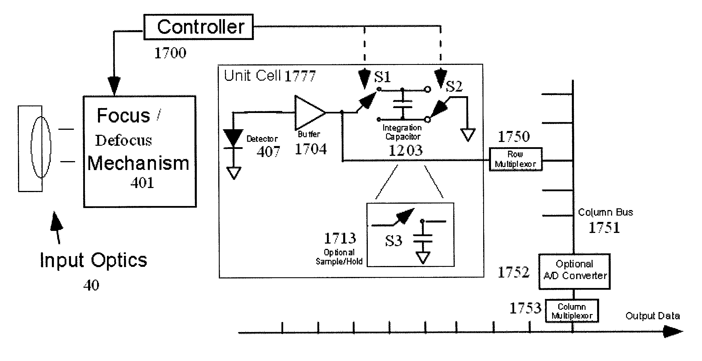

Image

  • Sensor apparatus and method for low-frequency scene suppression and fixed pattern noise suppression
  • Sensor apparatus and method for low-frequency scene suppression and fixed pattern noise suppression
  • Sensor apparatus and method for low-frequency scene suppression and fixed pattern noise suppression

Examples


Embodiment Construction

[0050]The invention being described may be varied in many ways. Such variations are not to be regarded as departure from the spirit and scope of the invention, and all such modifications are intended to be included within the scope of the following claims. Further, this invention can be applied to most systems, methods, and programs for example, systems, methods, and programs involving imaging, detection, and / or reconnaissance and targeting. Also, referring specifically to the figures, identical or similar parts are designated by the same reference numerals throughout this disclosure and therefore discussion of the same reference numerals will likely be only discussed in the first reference to that part. Thus, identical or similar parts are designated by the same reference numerals are assumed to be equivalent unless specified.

[0051]In order for improving performance aspects of the invention provides the use of a unique combination of optics focus adjustments, ROIC design, and / or im...


PUM


Abstract

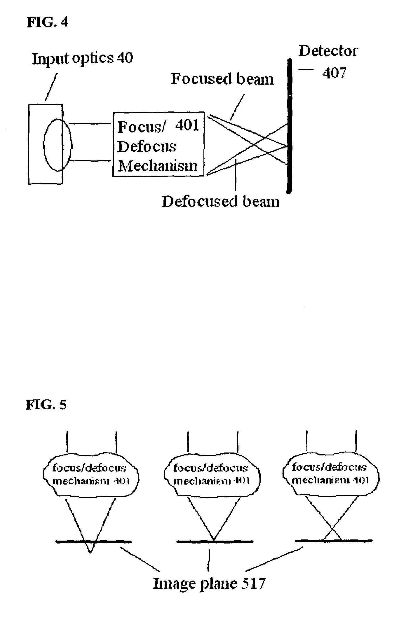
An imaging circuit comprises an image detector, accumulator coupled to the image detector, a focus / defocus mechanism focusing and defocusing an optical image onto the image detector; and a controller operatively connected to the focus / defocus mechanism, wherein the controller controls the focus / defocus mechanism to focus and defocus the optical image onto the image detector to provide focused and defocused images; where the controller controls the focus / defocus mechanism to focus the optical image onto the image detector to provide charge carriers of the focused image onto the accumulator, where the accumulator accumulates the charge carriers of the focused image, the controller controls the focus / defocus mechanism to defocus the optical image onto the image detector to provide charge carriers of the defocused image onto the accumulator, where the accumulator subtracts the charge carriers of the defocused image, and the imaging circuit reads out the charge carriers from the accumulator representative of a low pass filtered version of the focused image.

Description

FIELD OF INVENTION[0001]The present invention relates to improving the performance and image quality of imagers including focal plane array sensors.BACKGROUND OF THE INVENTIONDescription of Related Art[0002]Infrared (IR) imaging and detection is used for applications like target acquisition, surveillance, homing and tracking, remote temperature sensing, spectroscopy, and weather forecasting. Objects emit infrared radiation and the temperature of an object determines how much radiation is emitted and at what particular wavelength(s).[0003]The infrared spectrum is divided into spectral regions based primarily on how they are utilized in sensor systems. The five common regions of the infrared spectrum used include Near, Short, Medium, Long, and Very Long wavelength ranges.[0004]The first region, the Near Infrared (NIR), covers approximately 0.7-1 microns. The second region, the Short Wavelength Infrared (SWIR), covers approximately 1-3 microns. The third region, the Medium Wavelength I...

Claims


Application Information

Patent Timeline
Patent Type & Authority Patents(United States)
IPC IPC(8): H01L27/14G01J5/20H04N5/232
CPCG01J5/08G01J5/0806G01J5/084G01J5/22G02B7/08H04N5/23212G01J5/30G01J2005/0077
Inventor TENER, GENE D.GOODNOUGH, MARK A.
Owner LOCKHEED MARTIN CORP
Learn More