
System and method for on-line cleaning of black oil heater tubes and delayed coker heater tubes

a technology for oil heaters and coker heaters, applied in the direction of flush cleaning, lighting and heating apparatus, cleaning using liquids, etc., can solve the problems of affecting the cleaning effect of oil heaters, and requiring periodic operation shut-downs, so as to prevent the effect of tube fouling

Inactive Publication Date: 2010-03-02
GREAT SOUTHERN INDEPENDENT
View PDF3 Cites 11 Cited by
  • Summary
  • Abstract
  • Description
  • Claims
  • Application Information

AI Technical Summary

Benefits of technology

Significantly reduces or eliminates tube fouling, allowing black oil and delayed coker heaters to operate continuously without downtime, increasing refinery capacity and reducing maintenance needs.

Problems solved by technology

Although thermal cracking of the heated feedstock occurs primarily in the coking drum, there is some premature coking occurring in the radiant coker heater tubes which causes tube fouling.
Fouling of the internal walls of the coker heater tubes can cause blockages requiring periodic operation shut-downs to clean the tubes.
Modern delayed coking operations present the potential for rapid tube fouling due to increased feed rates and increased concentrations of fouling components in feedstocks such as asphaltenes, inorganics and heavy metals.
Usually, it is the capacity of the delayed coker heater which limits the refinery capacity.
However, the cleaning effectiveness of on-line spalling decreases each time it is performed.
Thus, on-line spalling only delays, but does not eliminate, the complete cleaning of the coker heater.
However, a disadvantage of this process is that the coker heater is required to be taken fully out of service anywhere from 1 to 3 days per heater.
However, a disadvantage of this process is that the coker heater is required to be taken fully out of service and heater tubes can be damaged if overheated.

Method used


Image

  • System and method for on-line cleaning of black oil heater tubes and delayed coker heater tubes
  • System and method for on-line cleaning of black oil heater tubes and delayed coker heater tubes
  • System and method for on-line cleaning of black oil heater tubes and delayed coker heater tubes

Examples


Embodiment Construction

[0035]The following discussion is presented to enable a person skilled in the art to make and use the invention. The general principles described herein may be applied to embodiments and applications other than those detailed below without departing from the spirit and scope of the present invention as defined by the appended claims. The present invention is not intended to be limited to the embodiments shown, but is to be accorded the widest scope consistent with the principles and features disclosed herein.

[0036]To the accomplishment of the foregoing and related ends, the invention comprises the features hereinafter fully described and particularly pointed out in the claims. The following description and the annexed drawings set forth in detail certain illustrative embodiments of the invention. These embodiments are indicative of but a few of the various ways in which the principles of the invention may be employed. Other objects, advantages, and novel features of the invention wi...


PUM

PropertyMeasurementUnit
pressureaaaaaaaaaa
temperatureaaaaaaaaaa
pressureaaaaaaaaaa

Abstract

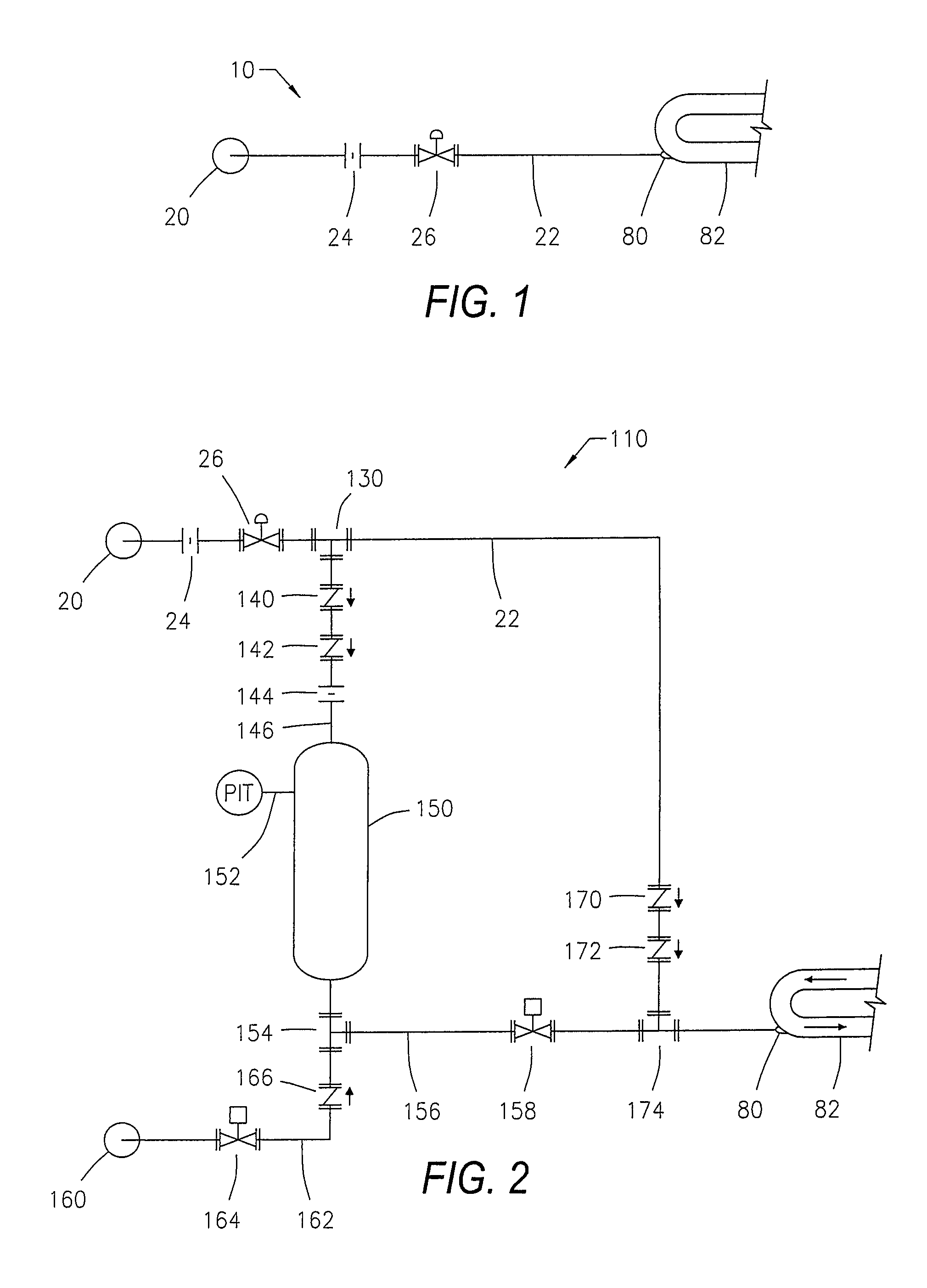
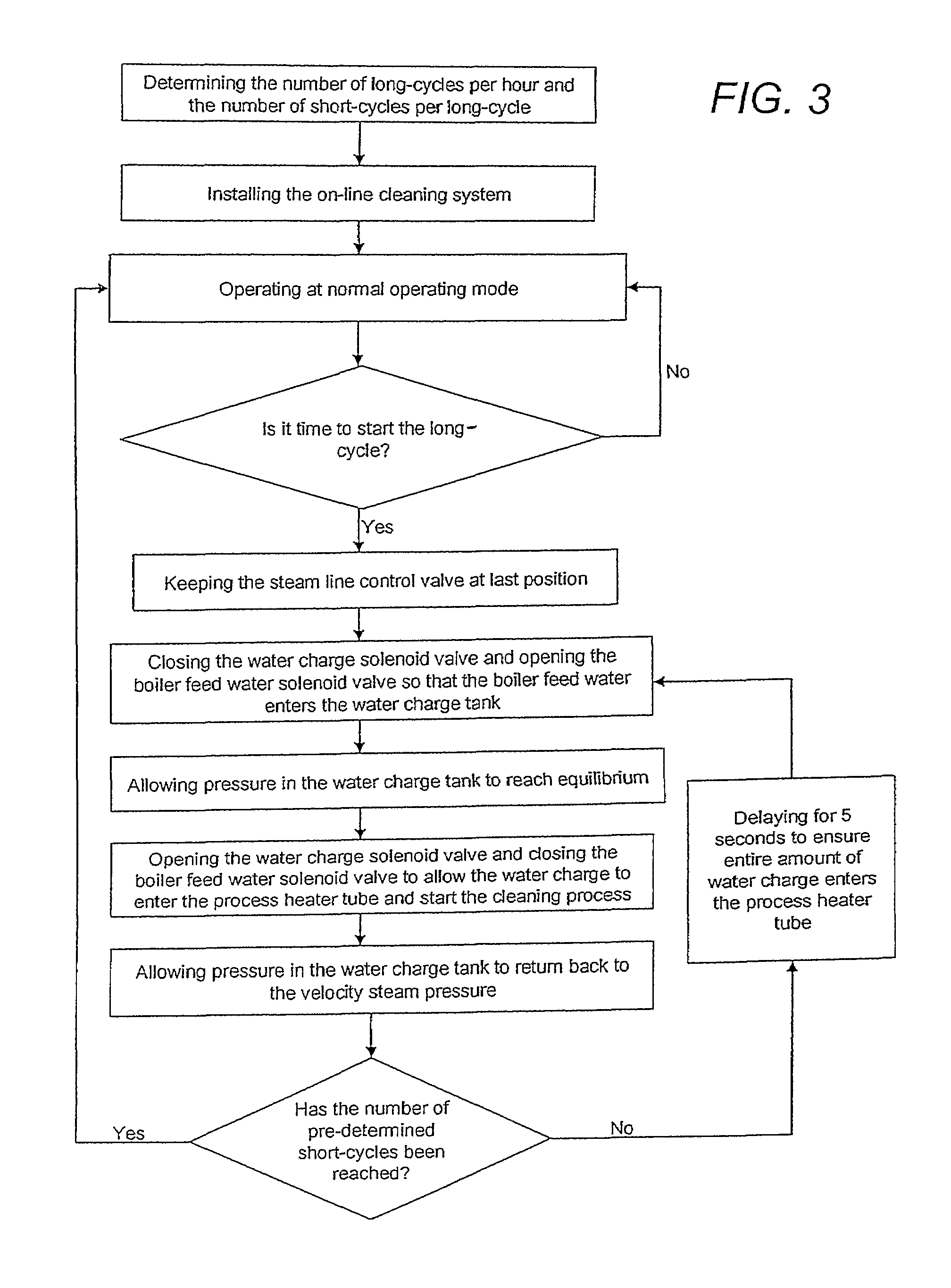
A system and method whereby on-line cleaning of black oil heater tubes and delayed coker heater tubes may be effectuated by injecting a high pressure water charge through the tubes during normal process operations so as to prevent tube fouling and heater downtime. The high pressure water charge begins the on-line cleaning process once it enters the heater tube by undergoing intense boiling and evaporation. The cleaning occurs by two methods—a scrubbing action and a shocking action. The scrubbing action occurs because of the complete turbulence caused by the water charge's intense boiling within the heater tubes. The shocking action is caused by the expansion and contraction of the heater tubes resulting from the colder water charge flowing through the heater tubes which is then followed by the hotter process fluid flowing through the heater tubes.

Description

CROSS-REFERENCE TO RELATED APPLICATIONS[0001]Not applicable.STATEMENT OF FEDERALLY SPONSORED RESEARCH / DEVELOPMENT[0002]Not applicable.THE NAMES OF THE PARTIES TO A JOINT RESEARCH AGREEMENT[0003]Not applicable.REFERENCE TO A SEQUENCE LISTING[0004]Not applicable.BACKGROUND OF THE INVENTION[0005]The present invention relates generally to black oil heaters and delayed coker heaters used in crude oil refining. More specifically, the present invention discloses a system and method whereby on-line cleaning of black oil heater tubes and delayed coker heater tubes may be effectuated by injecting a high pressure water charge through the tubes during normal process operation so as to prevent tube fouling and heater downtime. The present invention can be used for a variety of applications including, but not limited to, cleaning the tubes of crude heaters, vacuum heaters, visc breaker heaters, delayed coker heaters and any other heaters that have downstream equipment capable of handling the amou...

Claims


Application Information

Patent Timeline
Patent Type & Authority Patents(United States)
IPC IPC(8): C10B47/00B08B9/04F22B37/18
CPCB08B9/0321B08B9/0323C10G9/16F28G9/00
Inventor GIBSON, WILLIAM C.GIBSON, ROBERT L.
Owner GREAT SOUTHERN INDEPENDENT
Learn More