
Liquid crystal display device having sound

a display device and liquid crystal technology, applied in the direction of static indicating devices, instruments, portable computers, etc., can solve the problems of increasing the thickness of the device in which the display device is used, reducing the display quality, and not necessarily achieving the expected space saving effect of using the panel speaker as described abov

Inactive Publication Date: 2010-02-02
SHARP KK
View PDF17 Cites 68 Cited by
  • Summary
  • Abstract
  • Description
  • Claims
  • Application Information

AI Technical Summary

Benefits of technology

The present invention provides a liquid crystal display device with a light source that can add a sound output function without increasing external size or decreasing display quality. The device includes a liquid crystal panel with a connection terminal portion and an excitation source, and a light source near the edge of the panel. The light source can enter the panel from the side opposite to the excitation source, and the excitation source causes the panel to flexurally vibrate and produce sound. The device also includes a frame that causes the panel to flexurally vibrate and produce sound when an external sound source is added. The technical effects of the invention include preventing an increase in external size and maintaining high display quality.

Problems solved by technology

As a result, providing sufficient space for a speaker and a receiver (microphone) in a portable device also requiring a function for sound input and output has become increasingly difficult.
A problem with these methods of the foregoing prior art is that the thickness of the device in which the display device is used increases because the speaker is arranged over the display surface.
LCD devices commonly use a light emitting diode (LED) or other light source, and installation space for this light source competes with installation space for the exciter of the foregoing panel speaker in the edge portions of the LCD panel.
Using a panel speaker as described above therefore does not necessarily yield the expected space savings.
As a result, the external size of the LCD device increases when a sound output function is added, and this is particularly a problem with portable devices.
Furthermore, because the prior art as described above requires that a separate panel member be used as the speaker diaphragm in front of the display, the thickness of the frame (casing) in which the LCD device is housed is increased, and adding a sound output function causes a decrease in transmittance and thus degrades the quality of displayed images.

Method used


Image

  • Liquid crystal display device having sound
  • Liquid crystal display device having sound
  • Liquid crystal display device having sound

Examples


first preferred embodiment

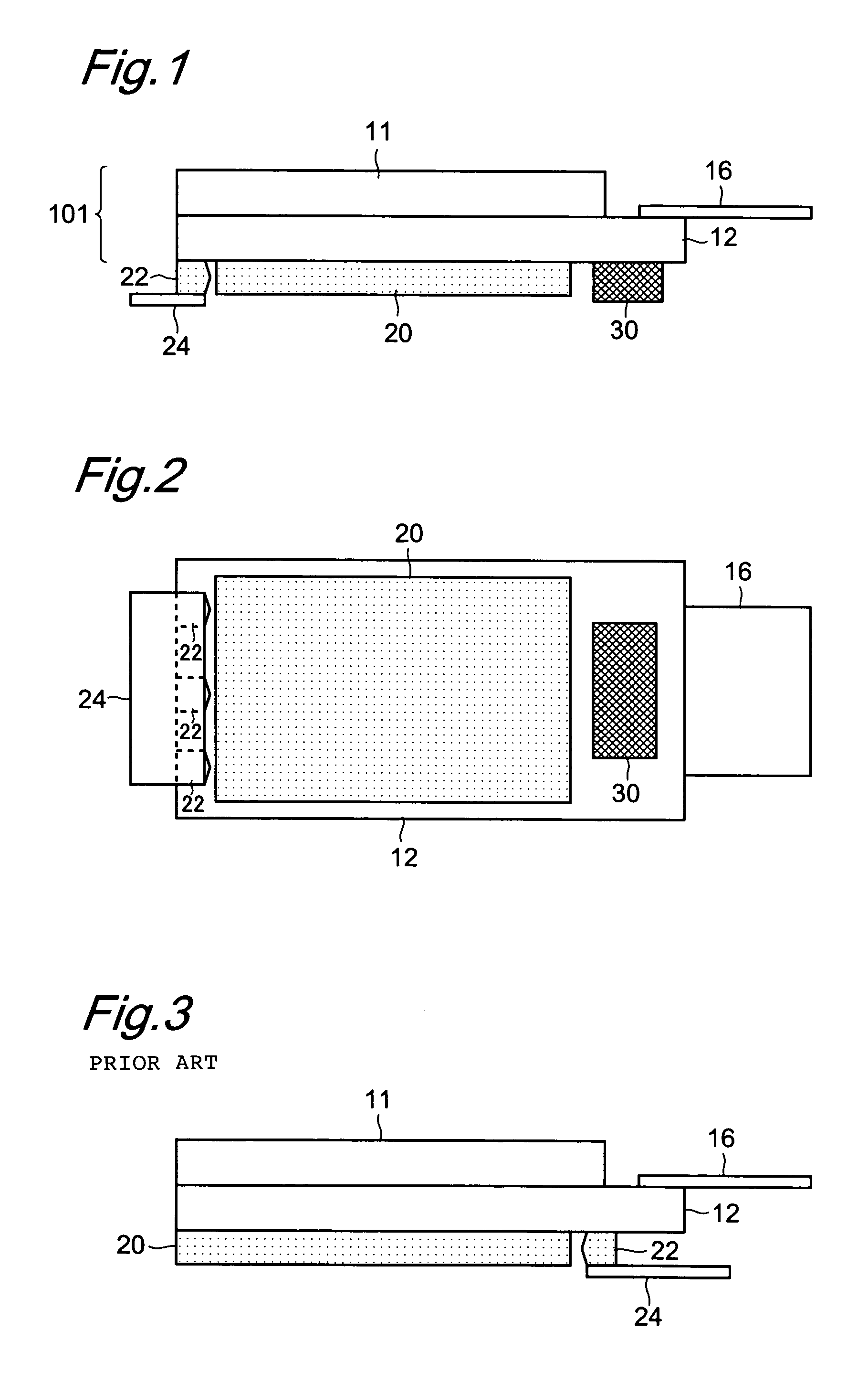
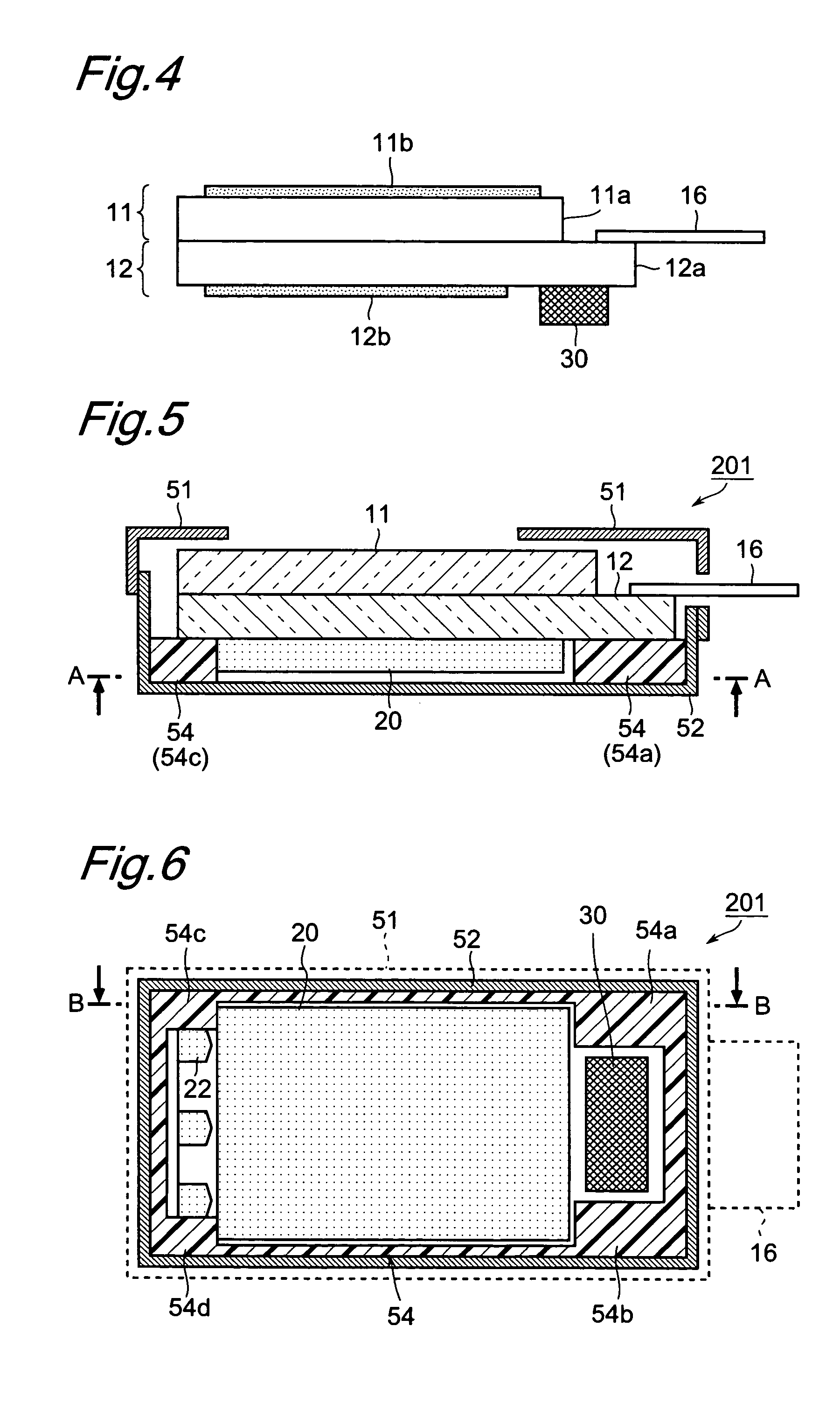
[0111]FIG. 1 is a side view showing the liquid crystal panel and the light guide plate, light source, and other parts associated therewith in a liquid crystal display device according to a first preferred embodiment of the present invention, and FIG. 2 is a bottom view of the LC panel shown in FIG. 1 as seen from the back side thereof. This LCD device 201 (see FIGS. 5 and 6) is preferably used as a liquid crystal display module in a portable electronic device such as a cell phone or PDA, and has a sound output function, that is, a speaker function, in addition to an image display function.

[0112]A liquid crystal panel 101 in this preferred embodiment of the present invention has a first substrate 11 and a second substrate 12 arranged to define a pair of opposing substrates. These substrates are fixed with a predetermined gap therebetween (typically several tens of microns). This gap is filled with a liquid crystal material, forming a liquid crystal layer. This LC panel 101 is transpa...

second preferred embodiment

[0127]FIG. 7 is a side view showing the liquid crystal panel and associated parts in an LCD device according to a second preferred embodiment of the present invention, that is, a side view of the LCD module, and FIG. 8 is a bottom view of the back of this LCD module.

[0128]As in the first preferred embodiment, an LC panel 102 according to the present preferred embodiment of the present invention preferably includes a pair of opposing substrates, a first substrate 11 and a second substrate 121. These substrates are fixed with a specific gap (typically several tens of microns) therebetween and have a liquid crystal layer formed by filling this gap between the substrates with a liquid crystal material. The LC panel 102 is also transparent or semi-transparent. Also as in the first preferred embodiment, an FPC 16 for supplying the signals required to display an image to the LC panel 102 is connected to the edge portion of the second substrate 121, and a light guide plate 20 is disposed on...

third preferred embodiment

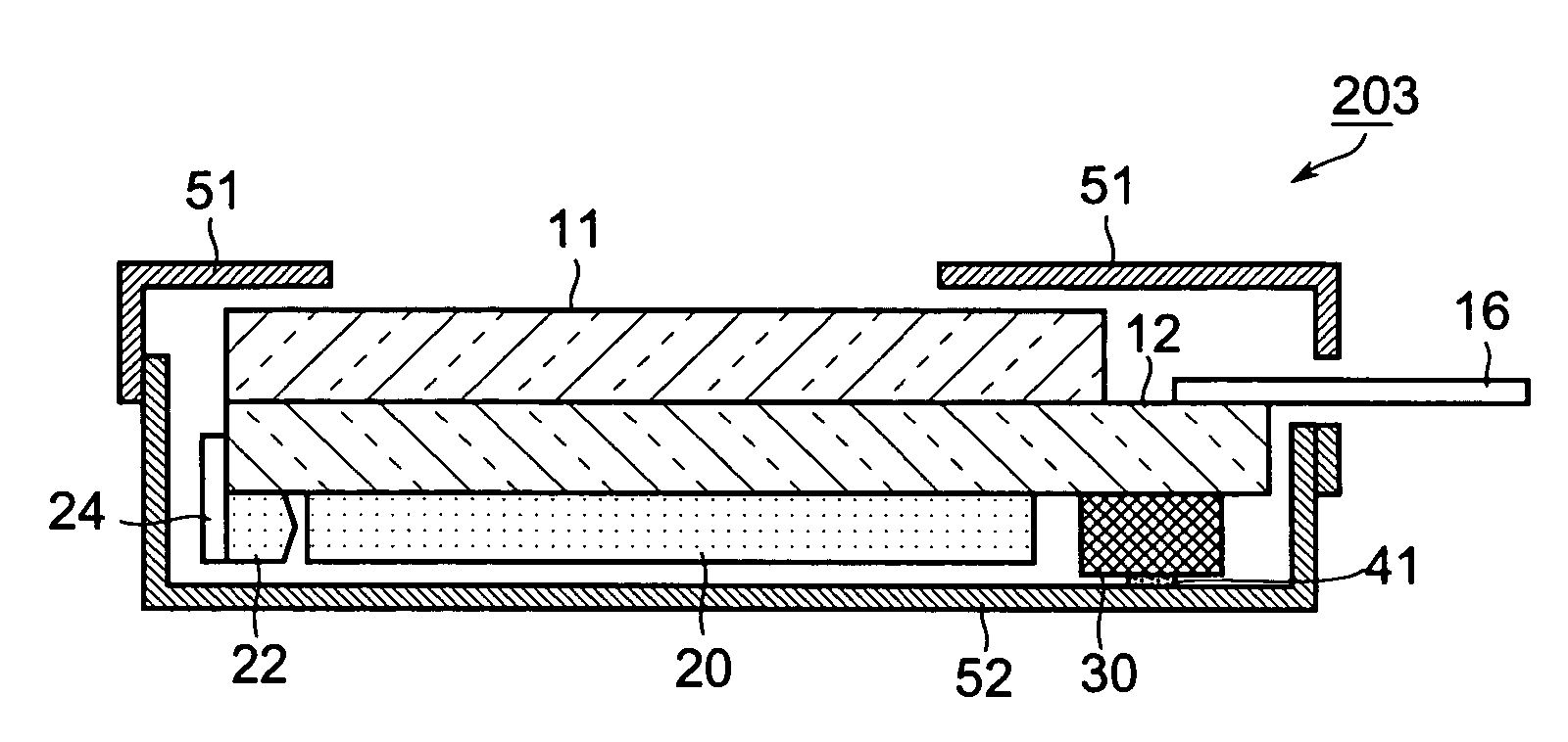
[0133]FIG. 10 is a longitudinal section view of an LCD device according to a third preferred embodiment of the present invention. Note that the chassis is omitted in FIG. 10 for simplicity.

[0134]As in the first preferred embodiment, this LCD device 203 is also used as a transparent or semi-transparent LCD module in a portable electronic device such as a cell phone or PDA, and has a sound output function (speaker function) in addition to an image display function. This sound output function is achieved by the excitation source 30 causing a substrate of the LC panel to flexurally vibrate according to a sound signal.

[0135]In the present preferred embodiment as shown in FIG. 10, however, the excitation source 30 is disposed in a position from which the excitation source 30 can cause the second substrate 12 of the LC panel to flexurally vibrate and is also mechanically bonded by an adhesive 41 to the rear bezel 52 so that the excitation source 30 can also cause the rear bezel 52 to flexu...


PUM

PropertyMeasurementUnit
phaseaaaaaaaaaa
sizeaaaaaaaaaa
weightaaaaaaaaaa

Abstract

A liquid crystal display device includes a sound output function. A sound output function can be added to a liquid crystal device having a light source while preventing any increase in the external size of the liquid crystal display device. The liquid crystal display device includes a liquid crystal layer sandwiched between a first substrate and a second substrate which oppose each other, a flexible printed circuit (FPC) connected to a brim portion of the second substrate, a light guide plate, and an LED. An excitation source is arranged at a portion corresponding to the back side of the FPC connection portion on the second substrate. The excitation source deflects and vibrates the second substrate of the liquid crystal display panel according to a sound signal from an outside source. That is, the second substrate is used as a vibration plate for the output of a sound. The liquid crystal display device can preferably be used for a liquid crystal module used in mobile devices such as a mobile telephone and a PDA.

Description

BACKGROUND OF THE INVENTION[0001]1. Field of the Invention[0002]The present invention relates to a liquid crystal display device used as a liquid crystal display module in various kinds of electronic devices, and relates more particularly to adding a sound output function to such a liquid crystal display device. The present invention can be used in any type of electronic device having a liquid crystal display device and is particularly well suited for use in a liquid crystal display module used in portable devices such as cell phones and PDAs.[0003]2. Description of the Related Art[0004]Liquid crystal display (LCD) devices are typically used as the display device in cell phones, PDAs (personal digital assistants), and other portable devices. Rising demand for greater display capacity in these LCD devices has meant that the LCD screen area has also tended to grow. Furthermore, as screen size has increased so has demand for size and weight reductions in the portable devices in which t...

Claims


Application Information

Patent Timeline
Patent Type & Authority Patents(United States)
IPC IPC(8): H04R25/00G02F1/133G06F1/16H04M1/03H04R7/04H04R17/00
CPCG02F1/133G06F1/1613G06F1/1637G06F1/1688H04M1/03H04R7/04H04M1/0266H04R2499/11H04R17/00G02F1/13
Inventor MIYATA, KAZUHIKO
Owner SHARP KK
Learn More